Top 5 Injection Molding Defects and How to Prevent Them
Understanding common injection molding defects — and how to prevent them — can save thousands of dollars in mold rework, delayed launches, and quality escapes. Most defects are preventable, and the earlier in the process you address the root cause, the cheaper it is to fix.
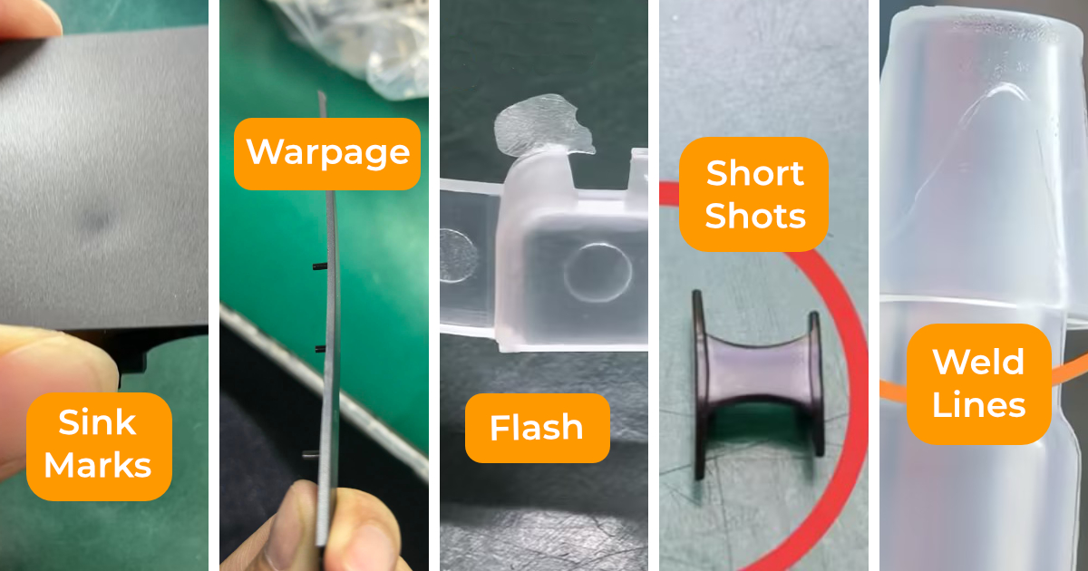
Here are the five most common injection molding defects, their root causes, and what you and your mold supplier can do to eliminate them.
1. Sink Marks
What it looks like: A visible depression or dimple on the surface of the part, typically on the opposite side of a thick section, boss, or rib.
What causes it: Sink marks occur when the outer skin of the part solidifies while the inner material is still cooling and shrinking. As the core contracts, it pulls the surface inward, creating a depression. The thicker the section, the worse the sink.
How to prevent it:
In part design:
- Keep wall thickness uniform — avoid abrupt transitions between thin and thick sections
- Design ribs at 50–60% of the nominal wall thickness (e.g. a 3mm wall → rib thickness max 1.8mm)
- Use hollow bosses or coring to reduce mass in thick sections
In mold design:
- Position gates closer to thick sections so pack pressure reaches them before the gate freezes
- Optimize pack pressure and pack time during process development
In process:
- Increase pack pressure and extend packing time
- Reduce melt temperature (reduces total shrinkage)
- Reduce mold temperature at thick areas (accelerates surface cooling)
Detection: Sink marks are visible under raking light. For appearance-critical parts, agree on a cosmetic standard with your supplier — define acceptable sink depth and location before production.
2. Warpage
What it looks like: The part comes out of the mold dimensionally distorted — bowed, twisted, or curved — rather than flat and true to drawing.
What causes it: Warpage occurs when differential shrinkage creates internal stresses in the part. Areas that cool faster or have different material orientation shrink differently, pulling the geometry out of shape.
Common triggers:
- Non-uniform wall thickness (one side cools faster)
- Asymmetric gate placement (uneven fill and orientation)
- Misbalanced cooling (one side of the mold runs cooler)
- Incorrect material choice for the geometry (high-shrinkage resins like PP and PE are most prone)
How to prevent it:
In part design:
- Design uniform wall thickness throughout
- Add ribs to flat large panels — they resist bending forces during cooling
- Avoid long flat unsupported sections in warpage-prone materials
In mold design:
- Run Moldflow simulation to predict warpage before tooling is cut
- Balance cooling circuits on both core and cavity sides
- Optimize gate location to produce symmetric fill
In process:
- Reduce injection speed (lower orientation stress)
- Increase cooling time
- Consider conformal cooling channels for complex geometries
Material note: Semi-crystalline materials (PP, PA, POM, PBT) warp significantly more than amorphous materials (ABS, PC, PMMA). If your geometry is susceptible to warpage and you have material flexibility, this is worth considering at the design stage.
3. Flash
What it looks like: A thin fin or web of plastic extending beyond the part edge, typically along the parting line, at ejector pins, or at vents.
What causes it: Flash occurs when molten plastic escapes from the mold cavity into the gap between mold components — the parting line, around ejector pins, at vents, or at side action interfaces.
Root causes:
- Insufficient clamping force — the injection pressure exceeds the force holding the mold closed
- Worn or damaged parting line surfaces — mold faces no longer mate tightly
- Oversized vent channels
- Excessive injection speed or pressure
How to prevent it:
In mold design:
- Design adequate clamping area (parting line area) to withstand injection pressure
- Maintain vent depths below the flash threshold for the material (typically 0.015–0.025mm for most resins)
- Ensure tight fit between core, cavity, and side action components
In mold maintenance:
- Inspect and re-stone parting line surfaces regularly — 1,000–2,000 shots if flash appears
- Check ejector pin fit and replace worn pins
In process:
- Reduce injection speed and pressure
- Reduce melt temperature
- Increase clamp force (if machine capacity allows)
Important note: Flash is often a mold wear issue in older tools. A new mold from a reputable supplier should be flash-free on T1 samples. If you receive a flashed T1, it indicates a mold design or machining issue that must be corrected before production.
4. Short Shots
What it looks like: The part is incomplete — an area of the cavity did not fill, leaving a void or missing section, usually at the last-fill point (far from the gate, or in a thin wall).
What causes it: The molten plastic ran out of pressure, heat, or flow path before filling the entire cavity.
Common causes:
- Insufficient injection volume (shot size too small)
- Insufficient injection pressure
- Melt temperature too low — plastic is too viscous to flow to the end of the cavity
- Thin walls that freeze before the melt front arrives
- Blocked or undersized gate restricting flow
- Inadequate venting — trapped air creates back-pressure
How to prevent it:
In part design:
- Avoid walls thinner than 0.8mm for most resins (0.5mm for PC, 1.0mm for PA66-GF)
- Add flow paths (thicker sections) to guide melt toward difficult-to-fill areas
In mold design:
- Increase gate size or add gates for large or thin parts
- Improve venting at last-fill areas (parting line, ejector pins)
- Run Moldflow simulation to identify potential short-shot locations
In process:
- Increase shot size
- Increase injection speed and pressure
- Increase barrel temperature
- Increase mold temperature
5. Weld Lines
What it looks like: A visible line or seam on the part surface where two melt fronts met during filling. May appear as a discolouration, a groove, or a line. In structural parts, weld lines represent a point of weakness.
What causes it: When molten plastic flows around a hole or obstacle (a pin, an insert, a window aperture) and the two melt fronts rejoin, a weld line forms. The junction has lower molecular bonding strength than the surrounding material because the fronts have already cooled partially when they meet.
Why it matters:
- Cosmetically: Weld lines are visible on gloss surfaces, especially with pigmented resins
- Structurally: Weld line strength can be 30–80% of the bulk material strength, depending on material and process conditions
How to prevent (or minimize) weld lines:
In mold design:
- Reposition the gate to place weld lines away from areas of cosmetic visibility or high stress
- Add overflow tabs or weld line traps at the weld location (machined away post-mold)
- For symmetrical parts, use multiple gates with matching weld line positions
In process:
- Increase melt temperature and mold temperature — hotter melt rejoins with better bonding
- Increase injection speed — melt fronts meet while still at higher temperature
- Increase pack pressure at the weld zone
In material selection:
- Amorphous materials (ABS, PC) generally produce stronger weld lines than semi-crystalline materials (PP, PA)
- Avoid glass-filled materials where weld line strength is critical — GF resins produce very weak weld lines
Summary
| Defect | Primary Design Cause | Primary Process Cause |
|---|---|---|
| Sink marks | Thick sections, heavy ribs | Insufficient pack pressure |
| Warpage | Non-uniform thickness | Imbalanced cooling |
| Flash | Inadequate clamp area | Excessive injection pressure |
| Short shots | Thin walls, poor venting | Insufficient temperature/pressure |
| Weld lines | Gate location near holes | Low melt temperature |
The best time to address all five defects is before the mold is built. A thorough DFM review and Moldflow simulation will identify every potential defect location — at a fraction of the cost of correcting them in steel.
JBRplas provides a free DFM analysis with every quote. Submit your part file and we’ll identify these risks before you commit to tooling.