I. Definition of Mold
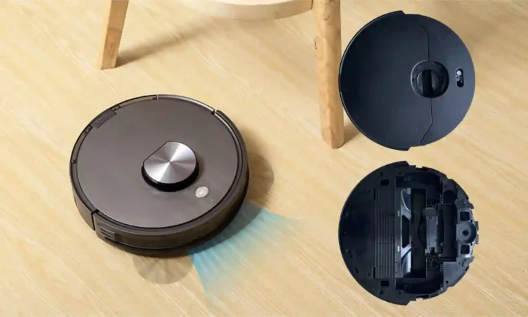
- Mold: A tool that shapes materials into products with specific dimensions. It determines manufacturing quality and cost, serving as the core tool for mass production, often referred to as the “Mother of Products.”
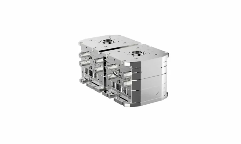
II. Overview of Plastic Injection Molds
- Working Principle
- Injection Process: Clamping → Plasticizing (feeding, decompression) → Injection (filling, packing) → Cooling → Ejection.
- Development Trends
- Larger molds, higher precision requirements, multi-functional composite molds.
- Increased use of hot runner systems, standardization of components, and advanced technological integration.
III. Classification and Applications of Plastic Molds
- Two-Plate Mold
- Structure: Direct separation of male and female molds. Suitable for single-cavity direct gates or multi-cavity edge gates.
- Applications: Simple products, e.g., parts with single-point gates.
- Three-Plate Mold
- Structure: Adds a runner plate for automatic gate separation. Suitable for multi-point gates (pin-point gates).
- Applications: Complex products requiring automatic gate cutting.
- Two-and-a-Half-Plate Mold
- Features: Heated runner system to maintain molten plastic, reducing waste and injection pressure.
- Hot Runner System
- Advantages:
- Shortens cycle time, improves efficiency;
- Reduces material waste;
- Lowers injection pressure, enhances product quality.
- Components: Hot nozzles, manifold, temperature controller, valve gate sequencer.
- Advantages:
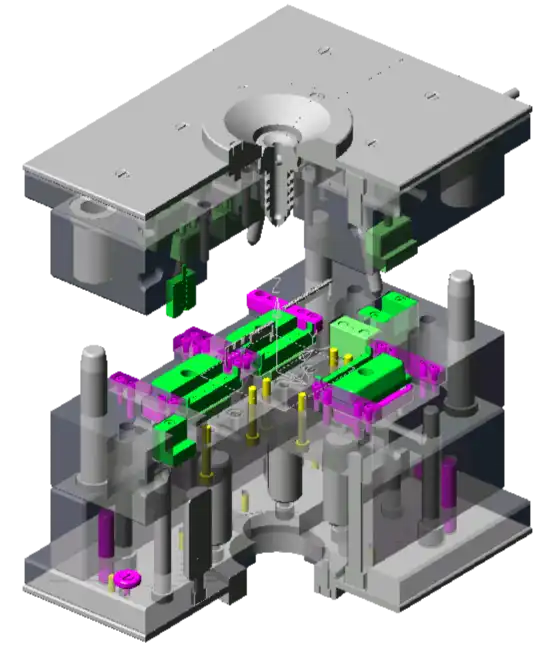
IV. Key Components: Functions and Layout
- Guide Pins (G.P.)
- Function: Ensure precise alignment of male and female molds to prevent core damage.
- Placement: Symmetrically at four corners; guide bushings on the female mold, pins on the male mold; includes vent slots.
- Ejector Guide Pins (E.G.P)
- Function: Guide movement of ejector plates.
- Quantity: Typically 4 (2 for small molds), placed near Return Pins (R.P.).
- Support Pillars (S.P.)
- Function: Reinforce male mold plate strength, prevent ejector plate deformation.
- Placement: Near high-pressure injection zones, avoiding interference with other components.
- Stopper Pins (STP)
- Function: Align injection nozzle with sprue bushing, reducing setup time.
- Specifications: Diameter Φ100 (small molds) to Φ150 (large molds), with tolerance (-0.10/-0.30 mm).
- Locating Ring & Sprue Bushing
- Locating Ring: Ensures nozzle alignment with mold runner.
- Sprue Bushing: Heat-treated for wear resistance; runners require draft angles.
- Small Pull Rods & Mold Locks
- Small Pull Rods: Utilize nylon friction for locking, suitable for low-volume or low-temperature molds.
- Mold Locks: Includes resin-type (high durability) and mechanical types for large or precision molds.
V. Injection Machine Selection and Guidelines
- Clamping Force Calculation
- Formula: Clamping Force (T) = 330 kg/cm2 × Product Length (cm) × Product Width (cm) × 1.5 / 1000
- Selection: Machine tonnage must exceed calculated value; ensure compatibility with mold thickness and tie-bar spacing.
- Knockout (KO) Holes & Lifting Holes
- KO Holes: Must align with sprue bushing; no positional deviation allowed.
- Lifting Holes: Sized based on mold weight; large molds require holes on all sides.
VI. Additional Notes
- Maintenance: Regularly inspect wear on guide pins, ejector pins, etc.
- Hot Runner Control: Strict temperature monitoring to prevent clogging or material degradation.