Wall Thickness Design Guide — How to Get Injection Molded Parts Right the First Time
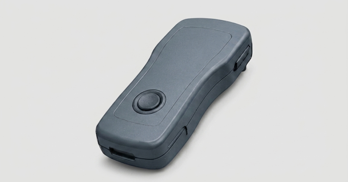
A product designer sends a CAD model for DFM review. The part is a handheld enclosure — ABS, two-piece clamshell, 180 × 95 × 35 mm. The nominal wall is 2.5 mm. The four screw bosses are 8 mm diameter with 6 mm walls. The snap-fit tabs are 4.5 mm thick where they meet the wall. The rim has a 7 mm solid bead for perceived quality.
The mold flows. The thick boss walls are the last to cool. As they shrink, they pull material from the adjacent wall surface. The result: a sink mark opposite every boss — a shallow depression 0.04 mm deep, invisible to touch on a textured part but glaring on a semi-gloss SPI B1 finish. The thick rim bead extends the cooling time requirement by 6 seconds — 6 seconds added to a 28-second cycle, or 21% more cycle time, for a feature that contributes nothing to function.
The fix costs $3,200 in mold modifications: the bosses are cored from the back side to thin the walls, the rim bead is hollowed out, and the snap-fit tabs are necked down at the attachment point. The DFM report that could have caught all three issues cost nothing but was never requested.
This guide covers the wall thickness design rules that prevent these problems — before steel is cut.
1. Why Wall Thickness Controls Everything
Wall thickness is the design variable that determines:
- Fill. Too thin, and the melt freezes before the cavity fills — short shots, flow lines, weld line weakness. Too thick, and the melt races through thin sections and hesitates at thick ones, creating imbalanced fill patterns.
- Cooling time. Cooling time is proportional to the square of wall thickness. A 3 mm wall takes 2.25× longer to cool than a 2 mm wall. The thickest section of the part determines the cycle time for the entire shot — every other section waits for it.
- Sink marks. Any local increase in thickness creates a heat reservoir that cools more slowly than the surrounding area. The differential shrinkage pulls the surface inward — a visible depression called a sink mark. On a textured surface (VDI 24 or similar), sink marks below 0.02 mm are invisible. On a glossy SPI A2 or B1 surface, a 0.01 mm depression is visible under directional light.
- Warpage. Non-uniform wall thickness produces non-uniform cooling, which produces non-uniform shrinkage, which produces internal stress, which produces warpage. A part that is flat when ejected can curl 0.5 mm overnight as residual stress relaxes.
- Part cost. Wall thickness drives material consumption and cycle time — the two largest contributors to per-part cost after tooling amortization. Reducing nominal wall from 3.0 mm to 2.0 mm cuts material cost by 33% and cycle time by approximately 55%.
Every DFM rule about ribs, bosses, gussets, and coring derives from a single principle: keep the wall thickness as uniform as possible. The molten plastic should see the same flow resistance and the same cooling rate everywhere in the cavity.
2. Nominal Wall Thickness — Where to Start
The nominal wall is the baseline thickness of the part — the thickness of the main surfaces before ribs, bosses, or other features are added. It is selected based on the material, the flow length, and the structural requirements:
- The material (each resin has a practical flow range)
- The flow length from the gate to the farthest point in the cavity
- The structural requirements (stiffness, impact, creep)
- The cosmetic requirements (thinner walls sink less but may fill less easily)
Recommended Nominal Wall Thickness by Material
| Material | Minimum (mm) | Typical Range (mm) | Maximum Practical (mm) |
|---|---|---|---|
| ABS | 0.8 | 1.2–3.5 | 4.0 |
| PC (Polycarbonate) | 0.9 | 1.5–3.5 | 4.5 |
| PC/ABS blend | 0.9 | 1.5–3.0 | 4.0 |
| PP (Polypropylene) | 0.6 | 1.0–3.0 | 4.5 |
| PA66 (Nylon 66) | 0.6 | 1.0–3.0 | 4.0 |
| PA66 GF30 | 0.8 | 1.5–3.5 | 4.5 |
| POM (Acetal) | 0.5 | 1.0–3.0 | 3.5 |
| PBT | 0.7 | 1.2–3.0 | 4.0 |
| PPS | 0.8 | 1.5–4.0 | 5.0 |
| PEEK | 0.8 | 1.5–4.0 | 5.0 |
| TPE/TPU | 0.5 | 1.0–3.0 | 4.0 |
| LCP | 0.3 | 0.5–1.5 | 2.0 |
The minimum values assume a flow length of approximately 100 mm from the gate. Longer flow lengths require thicker walls or higher melt temperatures to prevent premature freeze-off. For flow lengths exceeding 200 mm, increase nominal wall by 15–25%, or reposition the gate closer to the flow path midpoint.
Flow Length to Wall Thickness Ratio
The maximum practical flow length for a given wall thickness is material-dependent. The ratio varies:
| Material | Flow Length : Wall Thickness Ratio |
|---|---|
| PP (easy flow) | 250:1 – 300:1 |
| PA66 | 200:1 – 280:1 |
| ABS (general purpose) | 150:1 – 200:1 |
| POM | 120:1 – 180:1 |
| PC (standard viscosity) | 80:1 – 120:1 |
| PC (high flow) | 100:1 – 150:1 |
| PBT GF30 | 100:1 – 150:1 |
| PPS | 80:1 – 120:1 |
| PEEK (unfilled) | 60:1 – 100:1 |
A part with a 2.0 mm wall in general-purpose ABS can fill approximately 300–400 mm from the gate before the flow front cools below the no-flow temperature. If the farthest point in the cavity is 500 mm from the gate, options are: increase wall thickness to 2.5–3.0 mm, switch to a higher-flow ABS grade, add a second gate, or accept the risk and validate with mold flow analysis.
3. The Uniformity Rule — Managing Thickness Transitions
The ideal injection-molded part has the same wall thickness everywhere. Real parts have bosses, ribs, snap-fits, and mounting features that create local thickness variations. The design task is to manage those variations so they do not create problems.
Gradual Transitions
When wall thickness must change — at the edge of a rib, the root of a boss, or a step in the part profile — the transition should be gradual:
| Feature | Rule | Diagram Concept |
|---|---|---|
| Wall thickness step change | Maximum 15% change in thickness across the transition zone | Ramp, not step |
| Transition zone length | Minimum 3× the thickness difference | E.g., 0.5 mm change → 1.5 mm transition |
| Rib root to wall | 0.5–0.75 mm radius at the root | Prevents notch stress |
| Boss base to wall | 1.0–2.0 mm radius, or coring to maintain uniform section | Reduces sink and stress |
An abrupt step from 2.0 mm to 3.0 mm wall thickness — a 50% increase — creates a cooling differential. The thicker section stays molten 2.25× longer than the thin section. The resulting differential shrinkage concentrates stress at the step, and the thicker section will either sink (if near a surface) or produce a void (if buried in the interior).
The fix is a 1:3 ramp — 3 mm of transition length per 1 mm of thickness change — or better, redesigning the feature so the thickness change is not necessary.
Coring Out Thick Sections
Any solid section thicker than the nominal wall should be cored out from the back side or from a non-cosmetic face. This removes material from the center of the section while leaving the load-bearing outer shell intact. A solid boss with a 6 mm wall next to a 2.5 mm nominal wall is a guaranteed sink mark. A boss cored to a 2.0 mm wall with a 1.5 mm radius at the base will cool at the same rate as the nominal wall and produce no sink.
Coring also creates a bending-efficient section. A hollow cylinder has approximately 80% of the bending stiffness of a solid cylinder of the same outer diameter at 40% of the weight. The material removed from the center contributes little to stiffness — it exists primarily to extend cooling time and consume resin.
4. Rib Design — Stiffness Without Thickness
Ribs add stiffness to a plastic part without increasing the nominal wall. A rib is a thin, tall projection from the nominal wall surface that increases the section modulus perpendicular to the plane of the rib. A well-designed rib increases stiffness by a factor of 3–5× while adding only 15–25% to the part weight. Increasing the nominal wall to achieve the same stiffness would add 50–100% to the weight and 50–120% to the cycle time.
Rib Geometry Rules
| Parameter | Rule | Rationale |
|---|---|---|
| Rib base thickness | 0.5–0.7× nominal wall | Thinner than the wall to avoid sink on the opposite surface |
| Rib height | ≤3× nominal wall (typical), ≤5× (structural with draft) | Taller ribs risk filling difficulty and ejection problems |
| Draft angle | 0.5–1.5° per side (minimum), 1–2° (textured) | Necessary for clean ejection without drag marks |
| Root radius | 0.25–0.50× rib base thickness, min 0.3 mm | Reduces stress concentration at the rib-wall junction |
| Spacing between parallel ribs | ≥2× nominal wall | Prevents the ribs from creating a local thick section at the wall between them |
| Rib top radius | 0.25–0.50× rib top thickness | Avoids a sharp edge at the top of the rib |
The Sink Mark Limit
The critical ratio is rib base thickness to nominal wall thickness — T_rib / T_wall. At 0.5:1 (rib base = 1.0 mm, wall = 2.0 mm), a sink mark on the opposite surface is unlikely on any material. At 0.6:1 (1.2 mm rib on 2.0 mm wall), a sink mark is possible on glossy SPI/VDI surface finishes with semi-crystalline materials (PA, POM, PBT) but generally acceptable on textured surfaces. At 0.75:1 (1.5 mm rib on 2.0 mm wall), a sink mark is likely on glossy surfaces for most materials and will be visible on textured surfaces for semi-crystalline resins. Above 0.8:1, sink is expected — redesign the rib or core it from the back.
Cross-Ribbing Pattern
Intersecting ribs create a local thickness at the intersection that exceeds both individual rib thicknesses. The material volume at the intersection of two 1.0 mm ribs on a 2.0 mm wall is equivalent to a 2.0 mm thick section — producing a sink mark directly opposite the intersection. To avoid this:
- Stagger intersecting ribs so they do not meet at a single point
- Core the intersection from the back side if the cosmetic surface is opposite
- Reduce the rib thickness in the immediate vicinity of a four-way intersection
- Design the part so that the cosmetic surface is on the rib side (sink occurs on the non-cosmetic side)
5. Boss Design — Mounting Without Sink
Bosses are cylindrical projections used for screw fastening, alignment, or component mounting. A boss is the most thermally massive feature on most injection-molded parts — and the most common source of sink marks.
Boss Geometry Rules
| Parameter | Rule |
|---|---|
| Outer diameter | 2.0–2.5× screw diameter (for self-tapping screws in plastic) |
| Inner diameter | 0.8× screw diameter (pilot hole) |
| Boss wall thickness | 0.5–0.7× nominal wall (same as rib rule) |
| Boss height | ≤3× outer diameter for freestanding bosses |
| Base radius | 0.25× boss wall thickness, min 0.5 mm |
| Draft on ID | 0.5–1° (core pin side) |
| Draft on OD | 0.5–1° |
Isolating Bosses from Walls
A boss attached directly to a side wall creates a local thickness accumulation at the junction — the boss wall plus the part wall — that produces a sink mark on the exterior surface opposite the attachment point. The solution is to isolate the boss from the wall:
- Gusseted boss: Connect the boss to the wall with three or four thin gussets (0.5–0.7× nominal wall) instead of attaching the boss directly. The gussets provide lateral stability without creating a thick section.
- Free-standing boss with gussets: The boss stands alone in the cavity, connected to the base wall. Gussets at 120° spacing provide bending stiffness.
- Cored boss: The boss is formed by a hollow cylinder with a uniform wall — no thick section, no sink. The core pin that forms the inner diameter extends through the base of the part, creating a through-hole.
6. Material-Specific Wall Thickness Considerations
Amorphous vs Semi-Crystalline
Amorphous resins (ABS, PC, PS, PMMA) shrink less and more uniformly than semi-crystalline resins (PA, PP, POM, PBT, PPS). An amorphous resin at 2.5 mm nominal wall will produce less differential shrinkage between thick and thin sections than a semi-crystalline resin at the same geometry. This means:
- Amorphous resins are more forgiving of modest wall thickness variation. A 0.6:1 rib-to-wall ratio on ABS may produce no visible sink, while the same ratio on PA66 will produce a visible depression on a glossy surface.
- Semi-crystalline resins demand stricter adherence to the 0.5:1 rib ratio and uniform wall rules. The crystalline regions that form during cooling occupy less volume than the amorphous melt — this volumetric change produces more shrinkage and more sink sensitivity.
Glass-Filled vs Unfilled
Glass fibers reduce shrinkage by 50–70% compared to the unfilled resin. GF30 PA66 shrinks 0.3–0.5% versus 1.0–1.8% for unfilled PA66. This is an advantage for dimensional control, but it introduces two wall-thickness-related issues:
- Fiber orientation. In thin walls (<1.5 mm), glass fibers align strongly in the flow direction. This produces anisotropic shrinkage — more shrinkage perpendicular to flow than along it — and anisotropic mechanical properties (higher stiffness and strength along the flow direction). The part will warp toward the flow direction if the geometry is not symmetric about the gate.
- Minimum wall thickness. Glass-filled grades require a higher minimum wall than unfilled grades because the fibers increase melt viscosity. GF30 PA66 needs a minimum 0.8 mm wall versus 0.6 mm for unfilled PA66. Below these minimums, fiber orientation creates weak knit lines and inconsistent fill.
For glass-filled plastic parts, design the nominal wall at least 0.2–0.3 mm thicker than the unfilled equivalent, and position the gate so the flow path is symmetric about the part centerline.
7. The Draft Angle Relationship
Draft angle and wall thickness interact. A drafted wall is thicker at the base than at the top. On a 30 mm tall rib with 1° draft per side, a 1.0 mm top thickness becomes a 2.0 mm base thickness — doubling the local wall and violating the uniformity rule.
For tall features (height >10× the wall thickness), draft angle must be balanced against wall thickness:
- Ribs up to 15 mm tall: Standard 1° draft is acceptable. The base thickness increase is manageable.
- Ribs 15–30 mm tall: Reduce the rib top thickness so the base does not exceed 0.7× the nominal wall. A 25 mm tall rib with 1° draft and a 0.6 mm top gives a 1.5 mm base — 0.75× a 2.0 mm nominal wall, at the upper end of acceptable.
- Ribs >30 mm tall: Consider whether the rib can be replaced with a formed metal insert, a machined feature, or a separate component assembled after molding. Very tall ribs create ejection challenges, draft-related thickness issues, and filling difficulty at the rib tip.
8. Common Wall Thickness Mistakes and Fixes
| Problem | Cause | Fix |
|---|---|---|
| Sink mark opposite boss | Boss wall >0.7× nominal wall | Core boss to 0.5–0.6× nominal wall; add gussets for stability |
| Sink mark opposite rib | Rib base >0.7× nominal wall | Reduce rib base thickness; add radius at root instead of thickening |
| Warpage after ejection | Non-uniform cooling from thickness variation | Coring, material change, or gate repositioning to balance flow |
| Short shots at rib tips | Ribs too thin relative to height; melt freezes before tip fills | Increase rib draft, increase melt temperature, or reduce rib height |
| Voids in thick sections | Solid section >4 mm; outer skin freezes, interior continues to shrink | Core out the section, or add a geometric feature to create controlled void location |
| Splay on surface near thick sections | Material moisture concentrating in slow-cooling thick regions | Ensure proper drying (120°C × 4h for PC, 80°C × 4h for ABS); reduce thickness |
| Extended cycle time | Thick feature sets cooling requirement for entire part | Core out thick sections; verify whether thickness is structurally necessary |
9. The DFM Workflow for Wall Thickness
Before committing a design to tooling, run through this checklist:
- Set the nominal wall based on material, part size, and structural requirements. Document the number as a design rule for the project.
- Identify every feature thicker than the nominal wall. Ribs, bosses, rims, snap-fit tabs, gussets, sealing beads, aesthetic features.
- For each thick feature, ask: Can this be cored from the back? Can the thickness be reduced without compromising function? Is the thickness visible on a cosmetic surface?
- Apply the rib ratio rule: Every rib base ≤0.6× nominal wall. Every boss wall ≤0.6× nominal wall.
- Check transitions: No step change >15% in wall thickness. Every transition is ramped over ≥3× the thickness difference.
- Check draft: Ribs and bosses have minimum 0.5° draft. Tall features (>15 mm) have the draft-thickness tradeoff calculated.
- Run a mold flow analysis for parts with flow length >200 mm, wall thickness <1.0 mm, or more than 4 cavities. Simulation costs less than one mold modification.
- Get a DFM review from the tooling supplier before releasing the design. The supplier knows their machine capabilities, their steel-cutting tolerances, and the process window their shop can hold.
Summary
Wall thickness is not just a drawing dimension. It is the control parameter for fill, cooling, shrinkage, warpage, surface quality, and part cost. Every local thickening is a potential sink mark. Every abrupt transition is a potential stress concentration. Every unnecessary millimeter of wall thickness is money left in the cycle time.
The design rules are simple:
- One nominal wall, applied uniformly
- Ribs and bosses at 0.5–0.6× the nominal wall
- Gradual transitions wherever thickness must change
- Core out every section that can be cored
- Validate the design before cutting steel
The DFM review that catches these issues costs nothing. The mold modification that fixes them after the tool is built costs thousands.
This guide covers the design rules. For a DFM review of your specific part, contact our engineering team with a 3D model — wall thickness analysis, gate placement recommendations, and cycle time estimate within 24 hours.