Ultrasonic Welding for Plastic Parts — Joint Design, Material Compatibility, and Process Control
A product design team at a consumer electronics company is assembling a two-piece ABS enclosure — a base housing and a snap-on lid. The lid was designed with four snap-fit cantilevers along the perimeter. The snap-fit analysis predicted 18 N retention force per snap, adequate for the 40 N total required to keep the lid seated during drop testing. The first production run told a different story: 12% of units failed the 1-meter drop test, the lid separating from the base at the snap-fit engagement. The root cause was snap-fit relaxation after molding — ABS stress relaxation over the first 72 hours after molding reduced the retention force to 12 N per snap, 33% below the design value.
The fix was not stronger snap-fits. It was ultrasonic welding.
The same team received a second design constraint: the enclosure must achieve IP67 water and dust ingress protection. Snap-fits do not seal. Gaskets add a part, a process step, and a failure point. Solvent bonding introduces volatile organic compounds that the company’s sustainability policy prohibits. Adhesives require curing time that the automated assembly line cannot accommodate.
Ultrasonic welding solves all three problems in a single process: it permanently joins the lid to the base with a continuous hermetic seal, produces bond strength that exceeds the base material strength, and completes the weld in under 1.5 seconds per assembly — compatible with a 30-second takt time on a high-speed automated line.
How Ultrasonic Welding Works
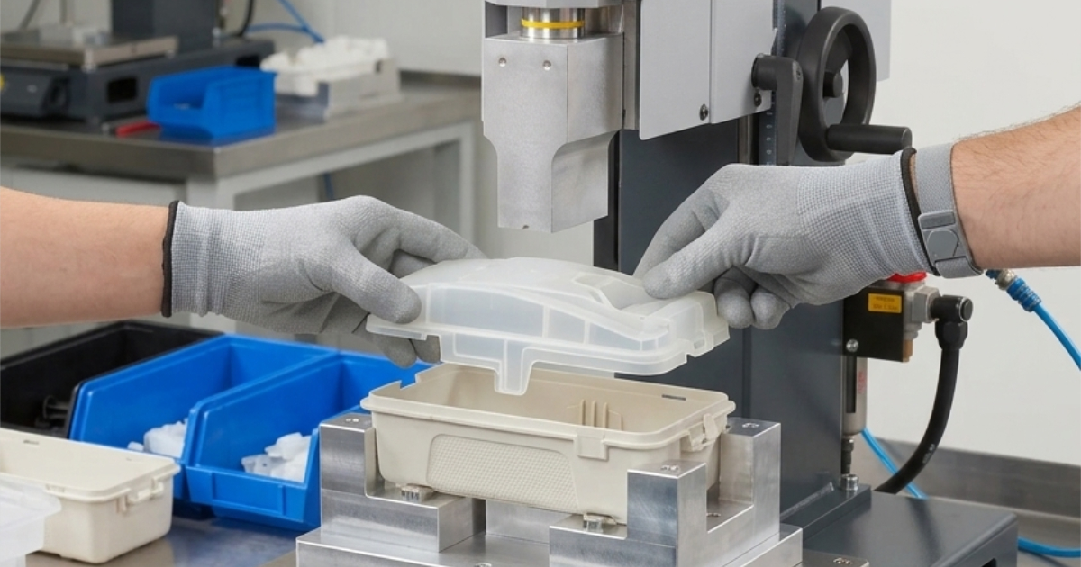
Ultrasonic welding converts 20–40 kHz electrical energy into mechanical vibration through a piezoelectric transducer (the converter). The vibration is transmitted through a metal tool (the horn or sonotrode) that contacts one of the two plastic parts. The parts are held together under controlled pressure in a fixture. The vibration generates frictional heat at the interface between the two parts, melting a thin layer of plastic at the joint. When the vibration stops, the molten plastic solidifies under maintained pressure, forming a homogeneous weld.
The process takes three parameters to describe — frequency, amplitude, and weld time — but the physics is localized melting at a designed contact point:
Power supply → Converter (electrical→mechanical) → Booster (amplitude adjustment) → Horn (transmits to part)
                                                                                            ↓
                                                                              Upper part → Energy director → Lower part
The vibration direction is vertical (perpendicular to the horn face), which means the joint geometry must provide a small initial contact area where the vibration energy concentrates. This is the energy director — a triangular ridge molded into one of the two parts at the joint interface. When the horn contacts the upper part and transmits 20 kHz vibration, the entire assembly vibrates, but the energy director tip — with its small cross-sectional area — experiences the highest frictional heating and melts first. The molten material flows across the joint interface, fills the gap between the parts, and solidifies into a continuous weld bead.
Joint Design — The Two Fundamental Types
Energy Director Joint (Standard Butt Weld)
The most common joint configuration for ultrasonic welding. A triangular ridge (energy director) is molded into one part at the joint plane. The ridge apex angle is typically 60° for amorphous plastics and 90° for semicrystalline materials. The ridge height is 0.3–0.6 mm depending on wall thickness.
| Wall Thickness | Energy Director Height | Peak Angle (Amorphous) | Peak Angle (Semicrystalline) |
|---|---|---|---|
| <1.5 mm | 0.2–0.3 mm | 60° | 90° |
| 1.5–2.5 mm | 0.3–0.4 mm | 60° | 90° |
| 2.5–4.0 mm | 0.4–0.6 mm | 60° | 90° |
| >4.0 mm | 0.5–0.8 mm | 60° | 90° |
The energy director melts progressively from the tip downward. The total collapse distance — the amount the horn travels downward as the energy director melts — is typically 0.2–0.4 mm. The fixture must accommodate this collapse without misaligning the parts.
Advantages: Simple mold geometry (the energy director is just a V-groove in the cavity), works with most amorphous plastics, fastest weld time.
Limitations: Semicrystalline materials (PP, PE, POM, nylon, PBT) do not melt as cleanly from an energy director as amorphous materials. The crystalline structure requires more energy to disrupt, and the molten material cools faster, reducing the flow distance across the joint. For semicrystalline materials, the 90° peak angle and taller energy director height partially compensate, but the weld strength will typically be lower than for an equivalent amorphous-material joint.
Shear Joint (Interference Fit Weld)
For semicrystalline plastics and applications requiring a hermetic seal, the shear joint provides a different approach. Instead of a triangular energy director, the two parts are designed with a slight interference fit — typically 0.2–0.4 mm per side — and the welding takes place as one part is forced into the other while vibrating. The melting occurs along the vertical side wall of the interference zone, not at a point contact.
| Feature | Energy Director Joint | Shear Joint |
|---|---|---|
| Best for | Amorphous plastics (ABS, PC, PS, PMMA) | Semicrystalline plastics (PP, PE, POM, nylon, PBT) |
| Weld strength | 85–100% of base material | 70–90% of base material |
| Hermetic seal | Possible with continuous ridge | More reliable seal |
| Flash | Minimal, controlled | Visible flash ring at joint |
| Mold complexity | Simple V-groove | Requires precise side-wall tolerances |
| Part alignment | Self-aligning | Requires guidance in tooling |
| Tolerance sensitivity | Moderate | High — interference fit is critical |
A shear joint requires the part design to include a lead-in chamfer (typically 30° for the first 0.5 mm) to guide the upper part into the lower part, a controlled interference zone (0.2–0.4 mm per side), and a flash trap recess that captures the displaced molten material. The interference dimension is determined by the material: amorphous plastics use 0.2–0.3 mm interference per side; semicrystalline plastics use 0.3–0.4 mm.
Step Joint
A variation on the energy director joint for applications where precise alignment of the two halves is critical. A step is molded into the lower part that registers the upper part in both the horizontal and vertical directions. The energy director sits on top of the step. The step joint is common in medical device housings where the parting line must be visually flush and the internal clearance to the PCB must be maintained within 0.2 mm.
Material Compatibility
Not all plastics can be welded to each other. The fundamental rule: only chemically similar thermoplastics produce reliable ultrasonic welds. The molten material from both parts must mix at the molecular level during welding — if the two polymers are chemically incompatible, the weld interface will be a mechanical interlock at best, with no molecular bonding. This constraint needs to be integrated into the material selection process during part design — choosing a material for ultrasonic weldability is a DFM decision that should happen before the mold is designed.
Weldability by Family
| Material | Welds to Itself | Welds to Dissimilar Materials | Notes |
|---|---|---|---|
| ABS | ✅ Excellent | ABS/PC blend only | Most weldable plastic. Broad amplitude tolerance |
| PC | ✅ Good | ABS/PC blend only | Requires higher amplitude than ABS |
| PC/ABS blend | ✅ Good | ABS, PC | Standard for electronics enclosures |
| PP | ⚠️ Fair | Not weldable to dissimilar | Semicrystalline; energy director joint unreliable, use shear joint |
| PE (HDPE, LDPE) | ⚠️ Fair-Poor | Not weldable to dissimilar | Lowest weldability; near-field welding preferred |
| PA6 / PA66 | ⚠️ Fair | Not weldable to dissimilar | Must be dry; moisture produces foamy weld |
| POM (Acetal) | ⚠️ Fair | Not weldable to dissimilar | Low coefficient of friction reduces heating |
| PMMA (Acrylic) | ✅ Excellent | — | Full transparency possible at the weld |
| PBT | ⚠️ Fair | Not weldable to dissimilar | Semicrystalline; shear joint preferred |
| PSU, PES, PEI | ⚠️ Fair-Good | Not weldable to dissimilar | High melt temp requires high amplitude |
| PEEK, PPS | ❌ Poor | Not weldable | Melt temp too high for standard US welding |
Near-Field vs Far-Field Welding
The distance from the horn contact surface to the joint plane determines whether the weld is near-field or far-field:
- Near-field (<6 mm from horn to joint): The vibration transmits efficiently through the material. Used for most small-to-medium parts where the horn can contact the upper part directly above the joint.
- Far-field (>6 mm from horn to joint): The vibration must travel through a greater material thickness, attenuating energy and reducing weld consistency. Amorphous plastics (ABS, PC, PS) transmit ultrasonic energy well and can be far-field welded up to 15–20 mm from the horn contact point. Semicrystalline plastics (PP, PE, POM) dampen ultrasonic energy rapidly and should be limited to near-field applications within 6 mm.
PP and PE are poor candidates for ultrasonic welding in general because their low modulus and high damping characteristics absorb ultrasonic energy throughout the part rather than concentrating it at the joint. When ultrasonic welding is the only option for PP or PE, a shear joint with near-field horn placement is the minimum requirement for a reliable process.
Process Parameters
Four parameters control the ultrasonic welding process:
| Parameter | Range | Effect |
|---|---|---|
| Amplitude | 15–60 μm (peak-to-peak) | Higher = faster melt, more flash. Too high = material degradation |
| Weld pressure | 0.1–0.5 MPa (at the joint) | Higher = faster collapse, less weld time. Too high = excess flash, horn marking |
| Weld time | 0.2–1.5 s (typical) | Time under vibration before hold begins |
| Hold time | 0.5–2.0 s | Time under pressure after vibration stops, allowing melt to solidify |
The amplitude is the most material-specific parameter:
| Material | Recommended Amplitude (μm) | Notes |
|---|---|---|
| ABS | 20–30 | Widest processing window |
| PC | 25–40 | Requires more energy than ABS |
| PC/ABS | 22–32 | Between ABS and PC |
| PA6/66 (dry) | 30–50 | High amplitude; must be dry |
| PP | 40–60 | Highest amplitude; shear joint only |
| PMMA | 15–25 | Low amplitude; melts easily |
| POM | 30–45 | Moderate amplitude |
| PBT | 35–50 | High amplitude; semicrystalline |
The horn material and design also affect energy transmission. Aluminum horns are the most common for prototyping and low-to-medium volume production — they machine easily and transmit ultrasonic energy efficiently. Titanium horns are used for high-volume production where horn wear from continuous operation is a concern — titanium has 2–3× the fatigue life of aluminum in ultrasonic service. Steel horns are used only for applications involving abrasive fillers (glass-filled materials) where even titanium would wear excessively.
Common Weld Defects and Root Causes
| Defect | Appearance | Root Cause |
|---|---|---|
| Cold weld (low strength) | Weld bead not fully formed; parts separate at joint | Insufficient amplitude, too short weld time, or horn too far from joint |
| Overweld (flash, burning) | Excess flash; brown or black discoloration at joint | Excessive amplitude, too long weld time, or insufficient joint gap |
| Horn marking | Visible indentation or texture on part surface at horn contact | Horn pressure too high, horn profile does not match part surface |
| Non-uniform weld | Weld bead varies around perimeter | Horn not parallel to joint plane; uneven pressure distribution; fixture flex |
| Internal component damage | Cracked PCB, dislodged connectors | Amplitude too high for assembly sensitivity; vibration damping insufficient |
| Incomplete melt | Energy director partially melted, part of weld unattached | Energy director height variation from molding; horn amplitude too low |
The most common cause of ultrasonic welding failure is not the welding process itself — it is the molded part quality. Process validation for ultrasonic welding follows the same IQ/OQ/PQ logic as injection molding: installation qualification of the welding equipment, operational qualification across the amplitude and pressure ranges, and performance qualification on production parts with destructive testing of weld strength. If the energy director height varies by 0.1 mm across the part perimeter (within normal molding tolerances), the horn contacts the taller sections of the energy director first, and those sections melt before the shorter sections begin to heat. The result is a non-uniform weld with high strength in some areas and no bonding in others.
The DFM remedy: design the energy director with height 0.3 mm for walls under 2 mm and 0.5 mm for walls over 2 mm. This provides adequate material volume for collapse while staying within the ±0.05 mm energy director height tolerance achievable in a production precision molding process.
Integration into the Assembly Process
Ultrasonic welding integrates into automated assembly lines as an in-line station:
- Loading — Operator or pick-and-place robot loads the two parts into the welding nest. The nest includes alignment pins that register to molded features on the lower part.
- Horn descent — Pneumatic cylinder brings the horn into contact with the upper part at controlled pressure (0.1–0.5 MPa at the joint).
- Weld — Ultrasonic vibration at 20 kHz, 0.2–1.5 second duration. Energy director melts and collapses.
- Hold — Vibration stops, pressure maintained for 0.5–2.0 seconds while the melt solidifies.
- Retract and unload — Horn retracts, welded assembly is removed from the nest.
Cycle time per assembly: 3–8 seconds total, with the weld time itself typically under 1.5 seconds. The limiting factor is not the welding speed but the loading and unloading of the fixture.
For the IP67 enclosure requirement: a continuous energy director ridge around the entire perimeter, with a minimum collapse distance of 0.25 mm, provides a hermetic seal when welded at parameters validated on a leak tester. The seal integrity should be verified with a pressure-decay leak test on 1:200 assemblies rather than relying on process parameters alone — a pinhole leak from a 0.05 mm gap in the weld bead is invisible to visual inspection but will fail IP67 submersion testing.
The consumer electronics team that started with failing snap-fits ultimately implemented an ultrasonic welding process with a continuous energy director ridge around the full perimeter of the ABS enclosure. Weld parameters: 20 kHz, 25 μm amplitude, 0.25 MPa joint pressure, 0.8 second weld time, 1.0 second hold time. The welded assembly passed the 1-meter drop test at 100% (zero failures in 500 test units) and achieved IP67 certification on the first submission.
Ultrasonic welding is not the solution to every plastic joining problem — snap-fits, screws, adhesives, and solvent bonding each have their place — but for applications requiring permanent assembly, structural bond strength, and hermetic sealing in a process compatible with automated production speeds, it is the default answer.