Thin-Wall Injection Molding — High-Speed, High-Pressure Processing for Wall Thickness Under 1.5 mm
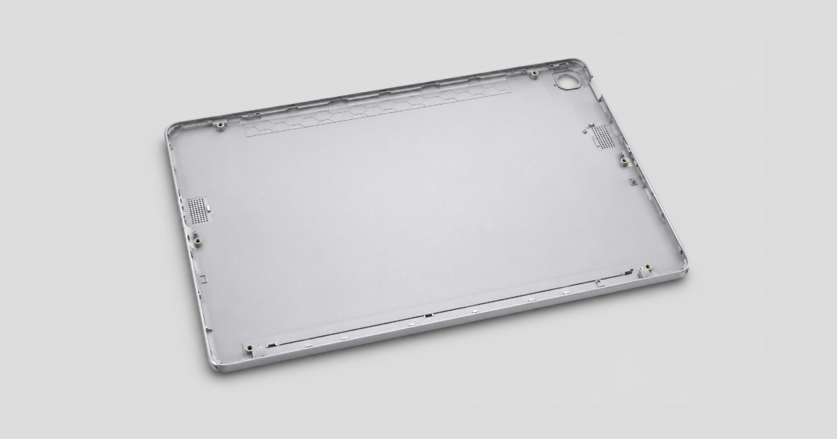
A product design team at a consumer electronics company is developing a next-generation tablet back cover — a PC/ABS enclosure measuring 250 × 175 × 6 mm, with a target wall thickness of 1.0 mm. The current-generation part uses a 1.8 mm wall, weighs 95 grams, and runs on a 280-tonne conventional press at a 32-second cycle. The new design goal: reduce weight to 55 grams, cut the cycle time to 12 seconds, and maintain the same 1-meter drop-test survival rate as the 1.8 mm version. The projected annual volume is 2.5 million units.
The team selects a high-flow PC/ABS blend with an MFR of 45 g/10 min — roughly 3× the flow rate of the standard 15 MFR grade used in the current part. The material flows adequately at 1.0 mm. But the mold flow analysis reveals a problem: the 1.0 mm wall requires a fill time of 0.35 seconds to prevent the flow front from freezing before the cavity extremities are reached. The existing 280-tonne press delivers a maximum injection speed of 160 mm/s — the required speed for a 250 mm flow length in 0.35 seconds is 550 mm/s. A standard press cannot fill a 250 mm long, 1.0 mm wall cavity before the melt freezes.
Thin-wall injection molding is not just about a hotter barrel, a faster injection speed, and a higher-flow material. It is a different injection molding process — one where the conventional assumptions about fill time, packing, cooling, and machine capability no longer apply.
What Defines Thin-Wall
The industry definition of thin-wall injection molding is a part with a nominal wall thickness less than 1.0 mm and a flow-length-to-wall-thickness ratio greater than 150:1. In practice, the definition centers on the process behavior rather than a dimensional cutoff: a thin-wall part is one where the fill time is less than the time required for the melt front to freeze against the cavity wall.
| Wall Thickness (mm) | Typical Fill Time (s) | Injection Pressure (MPa) | Flow Length Ratio | Typical Application |
|---|---|---|---|---|
| 0.3–0.5 | 0.05–0.15 | 180–250 | 200:1–300:1 | Micro-connectors, chip carriers (LCP) |
| 0.5–0.8 | 0.10–0.30 | 150–220 | 150:1–250:1 | Food packaging (PP), medical pipette tips |
| 0.8–1.2 | 0.20–0.50 | 120–180 | 100:1–200:1 | Electronics housings (PC/ABS), battery cases |
| 1.2–1.5 | 0.30–0.80 | 100–150 | 80:1–150:1 | Consumer electronics, appliance panels |
The fill time is the defining process parameter. In conventional molding, a 2.5 mm wall fills in 1.5–3.0 seconds — the melt front has time to travel from the gate to the cavity extremities before the skin freezes. In thin-wall molding, the 0.5 mm wall must fill in 0.1–0.3 seconds — the melt front is racing the freeze-off clock, and the machine must deliver the entire shot volume in less time than it takes a conventional press to reach its injection speed setpoint.
The Physics of Thin-Wall Filling
In a conventional wall, the plastic fills the cavity with a relatively slow-moving flow front, the frozen skin forms gradually, and the core of the wall remains molten long enough for packing to compensate for shrinkage. In a thin wall, three things are different:
1. The Fill-Time Window Narrows to Near Zero
The time available to fill the cavity before the flow front freezes is proportional to the square of the wall thickness. Reducing the wall from 2.5 mm to 0.8 mm reduces the available fill time by a factor of approximately 10× (2.5² / 0.8² ≈ 9.8). A part that fills comfortably in 2.0 seconds at 2.5 mm must fill in 0.2 seconds at 0.8 mm.
This is not a proportional relationship — it is a threshold. Above a critical fill time, the part fills completely. Below it, the flow front freezes mid-cavity and the part is a short shot. The threshold is material-dependent: amorphous materials (ABS, PC, PS) have a wider fill window because they lack a sharp freezing point; semicrystalline materials (PP, PE, PA, PBT) have a narrower window because crystallization releases latent heat that must be removed before the material solidifies, and the transition from melt to solid is sharper.
2. Injection Pressure Scales Inversely with Wall Thickness
The pressure required to fill a given flow length increases as the wall thickness decreases, because the flow channel is narrower and the melt viscosity is effectively higher (the colder cavity walls cool the melt more rapidly in a thin channel). For a PP part with a 150:1 flow length ratio:
| Wall Thickness (mm) | Injection Pressure (MPa) | Relative to 2.5 mm Baseline |
|---|---|---|
| 2.5 | 50–70 | 100% (baseline) |
| 1.5 | 80–110 | 160% |
| 1.0 | 120–160 | 240% |
| 0.7 | 160–200 | 320% |
| 0.5 | 200–250 | 400% |
The pressure increase has two consequences. First, the clamp force requirement increases proportionally: a 200-tonne press for a 2.5 mm wall part may need 350–400 tonnes for the same part at 0.7 mm. Second, the mold must be built to withstand the higher cavity pressure without deflection — thicker plates, more support pillars, and increased bolt preload are required.
3. Packing Becomes Nearly Irrelevant
In conventional molding, the packing phase compensates for 5–15% volumetric shrinkage by forcing additional melt into the cavity through the gate. In thin-wall molding, the gate freezes within 0.1–0.3 seconds after filling ends — before the packing pressure can act on the cavity. The part achieves its final dimensions through the filling phase alone, which means the shot size control must be more precise than in conventional molding. A shot-size variation of 1% on a 0.8 mm wall part produces a weight variation of approximately 2–3× that of the same variation on a 2.5 mm wall part, because the thin wall has less melt volume to absorb the variation.
Machine Requirements — Beyond a Standard Press
A conventional injection molding machine — designed for 2.0–3.5 mm wall parts with fill times of 1–3 seconds — cannot process thin-wall parts at production-viable cycle times. The machine must meet four specifications that exceed the conventional press envelope:
1. Injection Speed — Above 300 mm/s
Standard presses deliver injection speeds of 80–180 mm/s. Thin-wall presses deliver 300–800 mm/s. The injection speed determines the volumetric fill rate: for a given shot volume, the fill time is the shot volume divided by the volumetric injection rate. A 100 cm³ shot at 200 cm³/s fills in 0.5 seconds. At 400 cm³/s, it fills in 0.25 seconds.
The injection speed is delivered by a high-response servo drive with an accumulator or a direct-drive electric system capable of accelerating the screw from 0 to 500 mm/s in under 30 milliseconds. The acceleration phase consumes 10–15% of the available fill time — a press that takes 100 ms to reach its setpoint speed on a 200 ms fill window has already lost half the available time to acceleration.
2. L/D Ratio — Above 22:1
A high L/D (length-to-diameter) screw — typically 22:1 to 26:1, compared to 18:1 to 20:1 for conventional screws — provides more surface area for conductive heat transfer from the barrel to the pellets, and a longer compression zone for progressive melting without overheating. Thin-wall processing requires the melt to be at a uniform temperature with no unmelted pellet cores — an unmelted pellet in a 0.5 mm gate will block it instantly.
3. Clamp Force — 20–40% Higher Than Conventional
The injection pressure is higher, and the projected area of the cavity sees that pressure across its entire surface during filling. A part with a 300 cm² projected area at 160 MPa cavity pressure requires 480 tonnes of clamp force. The same part at 80 MPa requires 240 tonnes.
4. Shot-Size Precision — ±0.5% or Better
With packing nearly irrelevant, the shot size must be controlled within ±0.5% for consistent part weight. This requires closed-loop servo control of the injection stroke with position feedback at ±0.01 mm resolution on the screw position — the same class of precision expected in scientific molding process validation.
Material Selection — Flow Is Everything
Thin-wall molding is possible only with high-flow material grades. The melt flow rate (MFR) determines the viscosity at the processing temperature — higher MFR = lower viscosity = faster filling at a given pressure.
| Material | Conventional MFR (g/10 min) | Thin-Wall MFR (g/10 min) | Notes |
|---|---|---|---|
| PP | 10–20 | 35–100 | 100 MFR available for packaging |
| ABS | 5–20 | 25–50 | High-flow grades trade impact for flow |
| PC | 8–15 | 20–35 | High-flow PC has reduced molecular weight — lower impact |
| PC/ABS | 10–25 | 30–55 | High-flow blends maintain impact better than pure PC |
| PA6/66 | 10–30 | 40–80 | High-flow nylons for connectors |
| PBT | 10–25 | 30–50 | Glass-filled PBT for thin-wall connectors |
| LCP | N/A (inherently high flow) | N/A | Fills walls to 0.2 mm; the reference material for micro-thin-wall |
| POM | 5–15 | 20–40 | High-flow acetal for thin-wall gears |
The trade-off for high flow is almost always a reduction in mechanical properties — impact strength in particular. A 100 MFR PP has roughly 40–60% of the notched Izod impact strength of a 10 MFR PP. The material selection must balance the flow requirement against the minimum acceptable impact performance for the application. For a food container that only needs to survive stacking and transport, the impact reduction is acceptable. For an electronics housing that must survive a 1-meter drop test, the material must be validated at the thin-wall impact condition — the same material at 0.8 mm will absorb less impact energy than at 2.0 mm, independent of the MFR.
Gate Design for Thin Wall
The gate design for thin-wall parts differs from conventional practice in one critical respect: the gate must be large enough to fill the cavity in the available time without shearing the polymer to the point of degradation.
| Wall Thickness (mm) | Gate Depth (mm) | Gate Depth as % of Wall | Gate Width (mm) |
|---|---|---|---|
| 0.5 | 0.4–0.5 | 80–100% | 1.5–3× depth |
| 0.8 | 0.6–0.8 | 75–100% | 1.5–3× depth |
| 1.0 | 0.8–1.0 | 80–100% | 1.5–3× depth |
| 1.2 | 0.9–1.2 | 75–100% | 1.5–2.5× depth |
| 1.5 | 1.0–1.5 | 65–100% | 1.5–2.5× depth |
For conventional walls (2.0 mm+), the gate depth is 0.5–0.7× the wall thickness — the restriction at the gate is intentional, creating shear heating to improve flowability. For thin walls, the gate depth is 0.8–1.0× the wall thickness — the restriction is minimized because the wall itself is the dominant flow restriction, and additional restriction at the gate would require higher injection pressure than the machine can deliver.
Hot-runner valve gates are standard for thin-wall packaging and electronic parts where the gate vestige must be flush. For multi-cavity thin-wall molds (32–96 cavities for pipette tips, medical connectors, closures), the hot-runner system must be naturally balanced with identical flow-path lengths to every cavity — flow imbalance in a thin-wall mold produces a cavity-to-cavity fill-time variation that translates directly to part-weight variation and dimensional inconsistency.
The Cooling Paradox
Thin-wall parts cool faster than thick-wall parts — the 0.8 mm wall cools in approximately 1–2 seconds, compared to 12–18 seconds for a 2.5 mm wall. The total cycle time is dominated not by cooling but by filling, mold open/close, and part handling. A 0.8 mm wall PP container on a high-speed thin-wall press can achieve a total cycle time of 3–6 seconds, compared to 12–20 seconds for a conventional container.
The paradox: because the cooling time is so short, the cooling system design must remove heat at a higher rate than in conventional molding. The same amount of plastic (by weight) is processed per hour — but in half the cycle time, so the cooling system must remove heat at 2× the rate. Thin-wall molds require high-flow cooling circuits with turbulent flow in every channel, coolant delivery at 0–5°C (chilled water, not tower water), and the cooling channels placed as close to the cavity surface as the 2D rule permits — typically at 1.5D rather than 2.0–2.5D.
Thin-Wall by Application
Food Packaging — PP at 0.4–0.8 mm
The highest-volume thin-wall application. Margarine tubs, yogurt cups, deli containers, and microwaveable trays are molded in high-flow PP (35–100 MFR) at wall thicknesses of 0.4–0.8 mm. Single-cavity molds on high-speed accumulator presses produce 2–5 second cycle times. The parts are stacked, packed, and shipped at production rates exceeding 10 million units per year per mold. The limiting factor is not the molding process but the part handling — at a 4-second cycle, a robot must remove the part, stack it, and return to the mold in under 2 seconds.
Medical — Pipette Tips and Vials at 0.5–0.8 mm
Pipette tips are the ultimate thin-wall challenge: a conical part 50–120 mm long with a wall thickness tapering from 0.8 mm at the base to 0.3 mm at the tip, molded in PP or PE in 32–96-cavity molds. The flow length from the gate (at the base) to the tip is 120 mm through a wall that averages 0.5 mm — a flow-length ratio of 240:1. The mold must fill all 96 cavities uniformly before the flow front in any cavity freezes. The process window is measured in milliseconds.
Electronics — Battery Cases and Connectors at 0.5–1.0 mm
Smartphone battery cases, laptop bottom covers, and electronic connectors are molded in PC/ABS, PC, PBT, or LCP at walls of 0.5–1.0 mm. The requirements add cosmetic quality (no flow marks on visible surfaces) and structural integrity (drop-test survival) to the thin-wall filling challenge. The material must balance high flow (to fill the thin wall) with high impact (to survive the drop test) — a combination that makes high-flow PC/ABS blends the default material for consumer electronics thin-wall enclosures.
Thin-Wall vs. Conventional — Process Comparison
| Parameter | Conventional Molding | Thin-Wall Molding | Ratio |
|---|---|---|---|
| Wall thickness | 2.0–3.5 mm | 0.3–1.5 mm | 2–10× thinner |
| Fill time | 1.0–3.0 s | 0.05–0.5 s | 5–20× faster |
| Injection pressure | 60–120 MPa | 120–250 MPa | 2–3× higher |
| Injection speed | 80–180 mm/s | 300–800 mm/s | 3–5× faster |
| Cooling time | 8–30 s | 1–4 s | 5–10× shorter |
| Total cycle time | 15–45 s | 3–8 s | 3–6× shorter |
| Clamp force (for 300 cm² proj.) | 180–360 tonnes | 450–750 tonnes | 2–3× higher |
| Gate depth (% of wall) | 50–70% | 75–100% | Wider gates |
| Packing contribution | 5–15% weight | <2% weight | Packing nearly irrelevant |
| Shot-size tolerance | ±1.0% | ±0.5% | 2× tighter |
The electronics team’s tablet back cover project succeeded after replacing the 280-tonne conventional press with a 450-tonne high-speed thin-wall press with accumulator assist, 600 mm/s injection speed, a 24:1 L/D screw, and the 45 MFR PC/ABS. The 1.0 mm wall filled in 0.32 seconds at 165 MPa injection pressure. Cycle time: 11.5 seconds — a 64% reduction from the 32-second conventional cycle. The part passed the 1-meter drop test at 100% on the first qualification run. The weight reduction from 95 g to 55 g saved 100 tonnes of PC/ABS per year — at ¥35/kg, a material saving of ¥3.5 million annually, against a machine capital cost of ¥1.8 million.
Thin-wall injection molding is not a processing trick that can be dialed in on a standard press. It is a separate manufacturing discipline — one that combines a high-speed machine, a high-flow material, a mold built for 200+ MPa cavity pressures, and a part design that acknowledges the physics of filling a sub-millimeter channel before the plastic freezes.