Snap-Fit Design for Injection Molded Parts — Calculations, Materials, and Failure Modes
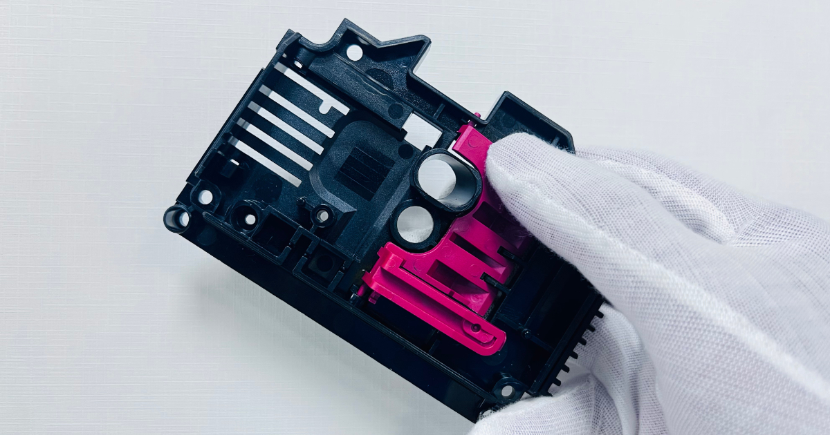
A snap-fit is a mechanical fastener formed entirely from the part material — no screws, no adhesives, no separate clips. The part is designed with an integral beam or tab that deflects during assembly and snaps back into a locked position. When it works, assembly is instant, tool-less, and permanent. When it fails, the beam breaks, the assembly rattles, or the snap loses retention force after a few insertion cycles.
Snap-fits are among the most efficient features in plastic part design — but only when the geometry, material, and mold design align. This guide covers the three main snap-fit types, the design calculations that determine beam life, material selection for snap-fit applications, and the mold design implications of the snap-fit geometry you choose.
Three Snap-Fit Types
1. Cantilever Snap-Fit
The cantilever snap-fit is the most common type — a beam projecting from the part wall with a hook or catch at the free end. During assembly, the beam bends to allow the catch to pass over the mating feature, then snaps back into the locked position.
Design parameters:
- Beam length (L): The distance from the beam root to the engagement face
- Beam thickness (h): The dimension in the direction of deflection
- Beam width (b): The dimension perpendicular to deflection
- Deflection (y): How far the beam tip must move to engage or disengage
- Undercut depth: The height of the catch feature that retains the mating part
The governing equation for a rectangular-section cantilever snap-fit:
Maximum strain at the beam root during deflection:
ε = (1.5 × y × h) ÷ L²
Where:
- ε = strain at the beam root (must be below the material’s allowable strain)
- y = required deflection at the beam tip (mm)
- h = beam thickness (mm)
- L = beam length (mm)
What this tells you: To reduce strain (and increase snap-fit life), increase the beam length or reduce the beam thickness. Doubling the beam length reduces strain to one-quarter. Halving the beam thickness reduces strain by half.
Design limits for a rectangular cantilever:
| Parameter | Guideline |
|---|---|
| Beam length (L) | 5–10× beam thickness for a standard snap; 3–5× for a stiff snap |
| Beam thickness (h) | 1.0–3.0mm typical |
| Deflection (y) | Maximum 0.5–1.5mm for most materials |
| Taper | 0.5°–1° per side along the beam length (improves stress distribution) |
| Root radius | Minimum 0.5mm at the beam base; 1.0mm preferred |
Tapered cantilever snap-fits distribute strain more evenly along the beam length than constant-section beams. Rather than concentrating all strain at the root, the taper spreads strain over the middle third of the beam — increasing fatigue life for the same deflection. A beam that tapers from full thickness at the root to 50% thickness at the tip reduces peak strain by approximately 30% compared to a constant-section beam of the same length.
2. Annular (Cylindrical) Snap-Fit
An annular snap-fit is a continuous ring of material around a cylindrical part — a cap, a lid, a connector shell. The ring deflects radially outward (or inward) during assembly and snaps into a mating groove. The entire circumference participates in the retention.
Design parameters:
- Ring diameter: Typically 10–60mm
- Ring cross-section: Rectangular or semi-circular
- Interference: 0.2–0.6mm per side (radial); 0.3–1.0mm for larger diameters
- Engagement angle: 20°–30° from the axis (shallow angle eases assembly)
- Retention angle: 45°–90° from the axis (steeper angle resists pull-off)
When to use annular vs cantilever:
- Annular: cylindrical parts, caps, connectors, continuous seal required, uniform retention force all around
- Cantilever: flat panels, enclosures, one-sided access, localized retention
Annular snap-fit design notes:
- The ring is formed by an undercut on the core side — typically requires a lifter or collapsible core to release. A simple two-plate mold cannot release an annular snap without a mechanism.
- Split-ring designs (a ring with one or more gaps) can be released without a lifter if the split aligns with the parting line and the gap allows the ring segments to flex inward during ejection.
- Mating grooves are formed in the cavity and require no special mold mechanism — only the snap ring itself is an undercut.
3. Torsion Snap-Fit
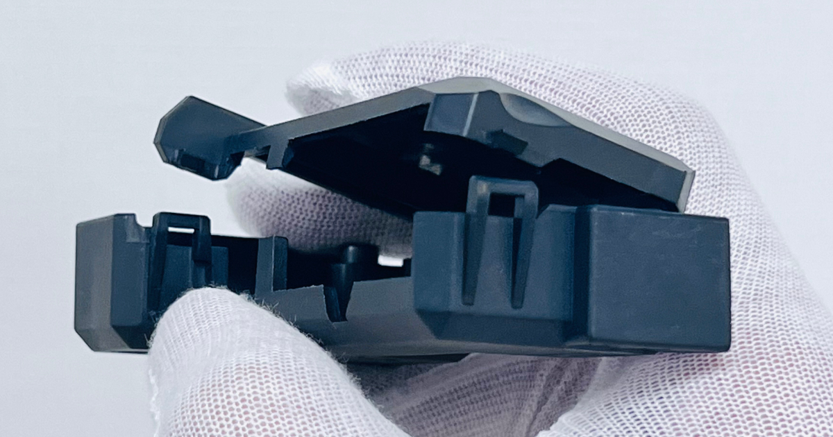
When to use:
- The snap feature must deflect in a direction perpendicular to the available beam length
- Space constraints prevent a cantilever beam of sufficient length
- The retention load is rotational rather than linear
Design principle: The torsion beam is typically a thin, wide section — wide in the plane perpendicular to the twist axis, thin in the plane of twisting. Thickness (t) and width (w) determine the torsional stiffness: stiffness ∝ w × t³.
Torsion snap-fits are less common than cantilevers because they require more complex mold geometry — the beam must be formed with a parting line that allows the twist axis to release. They are typically used in applications where a cantilever is geometrically impossible.
Material Selection for Snap-Fits
Not all plastics make good snap-fits. The key material property is allowable strain — how much the material can stretch before yielding or breaking. A material with high strain at yield can deflect further without permanent deformation. A material with high fatigue resistance can survive more insertion cycles.
Allowable Strain by Material
| Material | Strain at Yield (%) | Recommended Allowable Strain (%) | Snap-Fit Suitability |
|---|---|---|---|
| ABS | 2.5–3.5 | 1.0–1.5 | Excellent — the standard snap-fit material |
| PC | 6.0–7.0 | 2.0–3.0 | Good for single-snap; poor fatigue; notch-sensitive |
| PC/ABS | 4.0–5.0 | 1.5–2.0 | Excellent — better fatigue than PC, better strength than ABS |
| PA66 (unfilled, conditioned) | 25–40 | 3.0–4.0 | Excellent — but changes with moisture content |
| PA66-GF30 | 2.5–3.5 | 1.0–1.5 | Good strength; reduced strain due to glass fibre |
| POM | 8.0–12.0 | 2.0–3.0 | Excellent — high resilience, good fatigue; used for living springs |
| PP | 8.0–12.0 | 3.0–4.0 | Good for low-retention snaps; low stiffness limits holding force |
| TPE (Shore A 60–80) | > 50 | > 20 | Elastic deformation — snaps that are designed to stretch |
| PBT-GF30 | 2.0–3.0 | 0.7–1.0 | Limited snap-fits; low strain, brittle at low temperature |
Why PC has poor snap-fit fatigue: Polycarbonate’s high yield strain suggests good snap-fits, but PC is notch-sensitive — the sharp corner at the snap-fit root concentrates stress, and PC under cyclic loading initiates cracks at stress concentrations. A PC snap-fit that survives 5 insertions may fail at 50. For applications with repeated assembly/disassembly, PC/ABS or POM is a better choice.
Why PA66 depends on moisture: Dry-as-molded PA66 is stiff and relatively brittle — allowable strain around 2%. After conditioning to ambient humidity (2.5% moisture content), the material plasticises and allowable strain increases to 4% or more. If your snap-fit must work on day one (dry part, first assembly) and survive for years (conditioned), design for the dry allowable strain and accept the additional safety factor when conditioned.
Design Rules for Reliable Snap-Fits
1. Radius the Root
The beam root is the highest-stress location. A sharp corner at the root concentrates stress and initiates cracks. A root radius of 0.5mm minimum — ideally 1.0mm or 0.5× beam thickness, whichever is larger — distributes stress and improves fatigue life by 50–100% versus a sharp corner.
2. Avoid Weld Lines Through the Beam
If the gate location causes the weld line (where two melt fronts meet) to fall on the snap-fit beam, the beam will break at the weld line — regardless of how well the rest of the part is designed. Specify gate position to avoid weld lines in snap-fit features. If a weld line through the beam is unavoidable, increase the beam dimensions by 20–30% to compensate for the reduced strength at the weld line.
3. Design the Deflection Stop
The snap-fit beam should never be deflected beyond its allowable strain. A deflection stop — a physical feature that limits beam travel — prevents over-deflection during assembly. The stop should contact the beam or the mating part before the beam reaches maximum strain. It is a $0.00 feature that prevents the most common snap-fit failure mode.
4. Account for Molding Shrinkage
The beam dimensions in the mold are not the beam dimensions in the part. The mold steel is machined oversize by the shrinkage factor — typically 0.5–2.5% depending on the material. If the beam thickness is designed at 1.5mm in the CAD model, the mold cavity produces a beam 1.5mm thick. But the beam root radius, the catch geometry, and the interference with the mating part must all allow for the as-molded dimensions — including the tolerance band.
5. Gate Location Matters for Snap-Fits
The material’s molecular orientation at the snap-fit beam affects its strength. Plastic flowing along the beam length aligns polymer chains parallel to the beam — improving bending strength. Plastic flowing across the beam aligns chains perpendicular to the bending direction — reducing strength. Where possible, position the gate so that melt flows along the beam, not across it.
Mold Design Implications
Every snap-fit creates an undercut. The undercut must be released before the part can be ejected. How it is released determines tooling cost.
| Snap-Fit Type | Undercut Location | Mold Mechanism | Cost Adder |
|---|---|---|---|
| External cantilever (parting line) | At the part edge, in the plane of mold opening | None — released by cavity opening | $0 |
| External cantilever (side wall) | On a sidewall, perpendicular to mold opening | Side action (slide) | $1,000–$2,500 |
| Internal cantilever | Inside the part, projecting inward | Lifter | $800–$1,500 |
| Annular (continuous ring) | Internal or external ring undercut | Lifter or collapsible core | $1,500–$5,000 |
Design strategies to avoid mold mechanisms:
- Place snap beams at the parting line — the beam is formed half in the core, half in the cavity, and releases as the mold opens
- Use a window snap — cut a hole in the side wall and snap through the opening from outside; the hole is formed by a core pin (no mechanism)
- Use split-ring annular snaps — the gap allows the ring to flex during ejection
- Replace internal cantilevers with external ones — redesign the part to put the snap on the outside
Common Failure Modes
| Failure Mode | Cause | Prevention |
|---|---|---|
| Beam breaks during first assembly | Strain exceeds yield strain; sharp root corner | Increase beam length or reduce thickness; add root radius; check tolerance stack at worst case |
| Beam cracks after repeated assembly | Fatigue — cyclic strain exceeds endurance limit | Reduce allowable strain; select material with better fatigue properties (POM instead of PC) |
| Snap loses retention force over time | Creep — material relaxes under continuous load | Reduce continuous strain; select material with lower creep (PA66-GF30 instead of PP) |
| Snap fails at low temperature | Material brittle below Tg or at cold temperature | Select material with adequate impact at the lowest service temperature |
| Beam breaks adjacent to weld line | Weld line weakness in snap-fit area | Move gate to keep weld line away from snap beam |
| Snap engages but rattles | Tolerance stack — interference insufficient at min material / max mating | Increase interference; add secondary retention feature |
Frequently Asked Questions
How many times can a snap-fit be assembled and disassembled?
For a properly designed snap-fit in ABS or PC/ABS, 10–20 cycles is standard before noticeable retention degradation. For POM, 50–100 cycles is achievable. For TPE overmolded snaps, hundreds of cycles. The specification should be defined at the design stage — “this snap must survive 15 assembly cycles without loss of retention force exceeding 10%” — and validated with physical testing on production parts.
Can you add a snap-fit to an existing mold?
Adding a snap-fit to an existing mold usually requires adding a side action or lifter — which means machining into the existing mold steel. This is possible if the mold has sufficient steel thickness at the modification location and the modification does not compromise existing features. The cost is typically $1,500–$4,000 depending on the mechanism required. It is always cheaper to include the snap-fit in the original mold design.
What is the minimum snap-fit size for small parts?
A cantilever snap-fit of 3mm length × 1mm thickness × 2mm width is achievable in most engineering materials. Below these dimensions, the absolute deflection required for engagement may not be achievable without exceeding the material’s allowable strain. Micro-snap-fits in medical devices can go smaller but require tight process control and material-specific validation.
How do you validate snap-fit design before cutting steel?
Mold flow analysis with warpage simulation and FEA on the snap geometry at worst-case tolerance conditions. Prototype snaps can be milled from sheet stock for physical testing if the design is unproven. For critical snap-fits (safety, medical, automotive), a prototype aluminum tool with the snap geometry is the most reliable pre-production validation — it produces real molded parts with real material properties and real molecular orientation.
A well-designed snap-fit is engineered, not guessed. The beam dimensions are calculated from the material’s allowable strain. The root is radiused. The gate is positioned to keep the weld line away. The mold mechanism is specified before the tooling order, not discovered during mold design review. When these things are done, the snap-fit works — quietly, reliably, a thousand times over.
Submit your part for a free DFM review — including snap-fit feasibility analysis →