Sink Marks in Injection Molding — Root Causes and How to Prevent Them
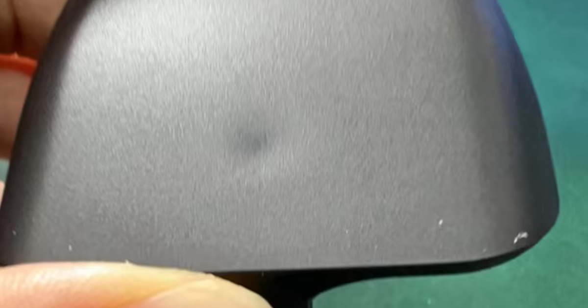
A quality engineer at a consumer electronics manufacturer is staring at a cosmetic reject. The enclosure is a matte black ABS part — 140 × 85 mm, 2.2 mm nominal wall, four M3 screw bosses on the internal face. The exterior is a Class A surface. Under the 800-lux inspection light, every boss location shows a shallow circular depression on the exterior — a sink mark approximately 6 mm in diameter and 0.03–0.05 mm deep. At arm’s length, the sink marks are invisible. Under the angled inspection light that the customer’s incoming QC uses, they are unmistakable.
The molding technician has increased the packing pressure from 60 MPa to 95 MPa, extended the hold time from 8 seconds to 16 seconds, and raised the mold temperature from 45°C to 62°C. The sink marks are shallower — perhaps 0.02 mm — but they are still there, and the cycle time has increased from 32 seconds to 41 seconds. The per-part cost has gone up by an estimated 22% from the extended cycle, and the sink marks have not been eliminated.
The root cause was not the process parameters. It was the boss wall thickness. At 2.8 mm, the boss wall was 1.3× the nominal wall — creating a localized thick section that cooled more slowly than the surrounding material. No amount of packing pressure compensates for a boss wall that violates the 0.5–0.6× rule.
What a Sink Mark Is (and What It Is Not)
A sink mark is a shallow depression on the surface of a molded part, typically occurring on the surface opposite a rib, boss, or wall thickness transition. The depression is not a void — it is a volumetric deficit. When a localized thick section of the part cools, the material in that section shrinks more than the material in the adjacent thin sections. The surface of the part — which has already frozen against the cavity wall — is pulled inward by the contracting material below it, creating the depression.
A sink mark is related to but distinct from a void:
| Feature | Sink Mark | Void |
|---|---|---|
| Location | On the part surface | Inside the part (internal) |
| Cause | Surface pulled inward by internal shrinkage | Internal material contracts, creating a vacuum bubble |
| Visibility | Visible on exterior, especially glossy surfaces | Not visible from the surface; detected by sectioning or X-ray |
| Common in | Cosmetic parts with bosses/ribs | Thick sections (>6 mm) with insufficient packing |
| Detection | Visual inspection under angled light | Weight check, CT scan, or destructive sectioning |
A sink mark is always above a thick section. If the opposite surface shows no corresponding rib, boss, or thickness transition, the defect is not a sink mark — it is more likely a flow mark, a weld line, or a gas mark.
The Physics: Why the Surface Drops
When molten plastic enters the cavity, it is at a uniform temperature and fills the entire cavity volume. The cavity is sealed by the frozen gate, and the part begins to cool. Cooling is not uniform — thin sections cool faster than thick sections.
In a 2.0 mm wall section, the plastic skin freezes against the cavity wall within 1–3 seconds. The core remains molten for another 5–10 seconds as heat conducts outward through the frozen skin. During this time, the core material undergoes thermal contraction as it cools from the melt temperature toward the mold temperature. The volumetric shrinkage of the core pulls against the frozen skin from the inside. In a uniform wall, the skin is uniformly supported by the internal melt, and it deflects evenly — typically below the threshold of visibility.
In a thick section — the junction of a 2.8 mm boss wall to a 2.0 mm nominal wall — the geometry is different. The thick section retains heat longer. The frozen skin forms later and is thinner. The core material in the thick section shrinks more (because it started at a higher temperature and has a larger volume of material to contract). The thin skin over the thick section deflects inward more than the skin over the uniform wall — creating the visible depression.
The depression depth is proportional to:
- The thickness difference between the thick section and the nominal wall
- The volumetric shrinkage of the material (higher shrinkage = deeper sink)
- The modulus of the frozen skin (higher modulus = more resistance to deflection)
This is why glass-filled materials show fewer and shallower sink marks: the glass fibers reduce both the volumetric shrinkage and increase the modulus of the frozen skin, resisting surface deflection.
The Four Levers for Sink Mark Prevention
Sink marks have four root causes, each with a different solution. The process technician who reaches for the packing pressure first — without checking the part design — is treating the symptom, not the cause.
Lever 1: Geometry — The 50% Rule
The single most effective sink mark prevention strategy is to never create the thick section in the first place. The rule: rib and boss wall thickness should be 0.5–0.6× the nominal wall thickness at the attachment point, and never exceed 0.7×.
| Nominal Wall (mm) | Max Rib/Boss Wall (mm) at 0.6× | Max at 0.7× (use sparingly) |
|---|---|---|
| 1.5 | 0.9 | 1.05 |
| 2.0 | 1.2 | 1.4 |
| 2.5 | 1.5 | 1.75 |
| 3.0 | 1.8 | 2.1 |
| 3.5 | 2.1 | 2.45 |
When a rib or boss needs to carry structural load and a 0.6× wall is insufficient, the solution is not to thicken the feature but to add more features — two 0.6× ribs instead of one 1.0× rib, or four bosses instead of two. The part design guidelines are clear: multiply the features, not the wall thickness.
For bosses specifically, three additional geometric remedies reduce sink:
- Core out the boss base. A recessed pocket at the base of the boss removes material from the thick junction zone, reducing the effective wall thickness at the transition. The pocket should be 0.8–1.0 mm deep and 1.5–2.0× the boss OD in diameter.
- Use a gusset instead of a continuous wall. Three or four gusset ribs (1.0–1.2 mm thick at 0.5× nominal wall) connecting the boss to the part wall provide structural support with less material than a continuous boss wall.
- Isolate the boss from the nominal wall. A 0.5–0.8 mm gap between the boss OD and the nearest part wall prevents the thick junction zone from forming. The boss is connected to the part through gussets that bridge the gap.
Lever 2: Process — Packing, Not Pressure
When geometry is already frozen (the mold is built), process changes can reduce sink mark severity — but not eliminate sink marks caused by a fundamental geometry problem.
Packing pressure (hold pressure): Additional melt is forced into the cavity after filling, compensating for the volumetric shrinkage as the part cools. The hold pressure must be sufficient to maintain melt flow through the gate until the gate freezes. Increasing hold pressure is the first response of most process technicians — and it works, up to a point. The limit is the gate freeze time: once the gate freezes, no additional melt can enter the cavity, and packing stops regardless of the pressure setting.
Hold time: The time that hold pressure is maintained. The hold time must be long enough for the gate to freeze while the hold pressure is still active. A gate that freezes during the cooling phase (after hold pressure drops) allows backflow from the cavity into the runner, creating sink marks and voids in thick sections. The hold time should be set by a gate-seal study: mold parts at increasing hold times (1-second increments), weigh each part, and plot part weight against hold time. The hold time at which part weight plateaus is the gate-seal time — hold times beyond this point add cycle time without benefit.
Mold temperature: A hotter mold delays skin formation, allowing the packing pressure to act on the core material for longer before the skin freezes. Raising mold temperature by 10–20°C can reduce sink depth by 30–50% — but at the cost of increased cooling time. The trade-off must be evaluated against the cost of cosmetic rejects.
Injection speed: A faster injection speed delivers hotter melt to the cavity extremities (less cooling in the runner), which improves filling of thin ribs and reduces the sink-producing temperature differential between thick and thin sections. The practical limit is the onset of jetting or gas entrapment at excessive speeds.
Lever 3: Material — Shrinkage Matters
Every plastic shrinks as it cools. The volumetric shrinkage from melt temperature to room temperature is a material property — and it varies by a factor of four across common injection molding materials:
| Material | Volumetric Shrinkage (melt → 25°C) | Sink Mark Tendency |
|---|---|---|
| PP (unfilled) | 14–18% | Very high |
| HDPE | 15–20% | Very high |
| ABS (general purpose) | 5–7% | Moderate |
| PC | 5–6% | Moderate |
| PC/ABS | 4–6% | Low-moderate |
| PA6/66 (unfilled) | 8–12% | High |
| PA6/66 (30% GF) | 3–5% | Low |
| PBT (30% GF) | 3–5% | Low |
| POM | 10–14% | High |
| PEEK (unfilled) | 6–8% | Moderate |
| PPS (40% GF) | 2–4% | Very low |
When sink marks are a persistent problem and geometry and process adjustments have reached their limits, the material choice may be the remaining lever. Switching from an unfilled to a glass-filled grade of the same polymer family reduces shrinkage by 50–70% and correspondingly reduces sink mark depth. The trade-off is increased tool wear from the glass fibers and changes to the mechanical properties that the design may or may not accommodate.
Lever 4: Gate Location — Feed the Thick Section
The gate location determines where the packing pressure acts. A gate that feeds directly into a thick section delivers packing pressure where it is most needed — at the thick-to-thin transition where the sink mark forms. A gate that feeds a thin section remote from the thick section creates a situation where the thin section freezes first, blocking the packing pressure from reaching the thick section that needs it.
The rule: locate the gate so that the melt flow path goes from thick to thin, not thin to thick. This is the same fill pattern rule that governs gate placement for general part quality, but it has specific relevance to sink marks — the gate must remain open and delivering hold pressure to the thick section until that section is adequately packed.
Mold Flow Analysis Validation
Mold flow simulation predicts sink mark locations and relative severity before steel is cut. The simulation calculates the cooling rate at every node on the part surface, identifies regions where the cooling rate is lower than the surrounding area (indicating a thicker section), and predicts the surface deflection caused by differential shrinkage. The output is a sink mark index — a dimensionless number from 0 (no sink mark) to a material-specific maximum that correlates with visible sink depth.
A sink mark index above 0.5 on a Class A surface is likely to produce a visible defect. Values below 0.3 are generally below the threshold of detection under standard inspection lighting.
The simulation allows the designer to test geometric remedies — boss wall reduction, core-out addition, gusset substitution — before committing to tool steel. A DFM review that includes mold flow analysis with sink mark prediction typically identifies 80–90% of sink mark locations that will require attention during mold sampling.
When a Sink Mark Is Acceptable
Not every sink mark is a reject. The acceptability depends on the cosmetic class of the surface:
| Cosmetic Class | Sink Mark Allowance | Typical Part Types |
|---|---|---|
| Class A (visible, critical) | None visible under 800 lux at any angle | Automotive interior trim, consumer electronics housings, appliance fascias |
| Class B (visible, non-critical) | ≤0.02 mm depth over ≤8 mm diameter, not visible at 500 mm distance | Internal covers, industrial equipment housings, functional enclosures |
| Class C (non-visible or covered) | ≤0.05 mm depth, texture can mask minor sink | Underside surfaces, internal brackets, parts covered by labels or overlays |
| Functional (no cosmetic requirement) | Any depth that does not compromise mechanical function | Internal structural components, parts assembled into a larger system |
The critical question during DFM review is: which surfaces are Class A, and are there thick features on the opposite side of those surfaces? If the answer is yes to both, the boss or rib design must be addressed before the mold is built — because process adjustments alone cannot eliminate a sink mark caused by a 1.3× rib-to-wall ratio.
The quality engineer who started with sink-marked cosmetic enclosures eventually addressed the root cause: the boss wall was reduced from 2.8 mm to 1.3 mm (0.6× the 2.2 mm nominal wall), a 1.0 mm deep core-out was added at each boss base, and the bosses were connected to the part wall with three 1.0 mm gussets instead of a continuous boss wall. The revised mold produced parts with no visible sink marks at the boss locations under 800-lux inspection. The cycle time returned to 32 seconds. The packing pressure was reduced to 70 MPa. The per-part cost returned to the original quotation.
Sink marks are not a molding problem that happens to be visible on the surface. They are a design problem that the molding process makes visible. Fix the geometry first, then tune the process.