Precision Injection Molding in a Clean Room — Why Temperature and Humidity Decide Your Tolerances
A payment terminal housing we mold holds ±0.2mm across a 106mm card swipe path — a tolerance the customer specified because magnetic stripe reading fails when the track drifts. First article passed. The mold was signed off. Eight months later the same customer reported intermittent swipe failures on units assembled in winter.
Nothing in the process had changed. The mold was the same, the process sheet was the same, the resin lot was traceable and in specification. What changed was the temperature of the part at the moment it was measured and at the moment it was assembled.
That is the part of precision molding that drawings do not capture. A dimension on a drawing is a single number. The dimension of a molded plastic part is a function of the material, the part’s current temperature, and its current moisture content.
Why a Molded Part’s Dimension Is Not a Fixed Number
Steel holds its dimensions. Plastic does not. Two mechanisms move a molded part after it leaves the mold, and both are continuous rather than one-time events.
Thermal expansion
Every thermoplastic has a coefficient of linear thermal expansion (CLTE) roughly one order of magnitude larger than steel. Typical values, in µm/m·K measured in the flow direction:
| Material | Typical CLTE (µm/m·K) | Notes |
|---|---|---|
| PEEK | 40–50 | Filled grades lower |
| PC | 65–70 | Amorphous, isotropic |
| ABS | 70–100 | Amorphous |
| PA66 (unfilled, dry) | 70–100 | Rises sharply with moisture |
| PBT | 70–100 | Semi-crystalline |
| POM | 100–120 | Semi-crystalline |
| PP (unfilled) | 100–180 | Highest of the common engineering resins |
| PA66-GF30 | 20–40 flow / 60–100 cross-flow | Strongly anisotropic |
Values vary by grade, additive package, and direction. Take the number from the resin datasheet, not from a table like this one.
The arithmetic is simple and unforgiving:
ΔL = L × α × ΔT
A 10°C ambient swing on a 106mm dimension moves it by:
| Dimension | Material | ΔT = 10°C | Tolerance band | Share of band |
|---|---|---|---|---|
| 6.10mm test strip slot | ABS (medical) | 0.004–0.006mm | ±0.03mm | 7–10% |
| 32.6mm probe housing OD | PEEK | 0.013–0.016mm | ±0.05mm | 13–16% |
| 106mm swipe path | PC | 0.069–0.074mm | ±0.2mm | 17–19% |
| 106mm swipe path | POM | 0.106–0.127mm | ±0.2mm | 27–32% |
| 106mm swipe path | PP (unfilled) | 0.106–0.191mm | ±0.2mm | 27–48% |
The first three rows are real JBRplas parts: the blood glucose meter housing test strip slot at ±0.03mm, the water quality sensor housing probe body in PEEK, and the POS terminal housing swipe path.
Two things follow from that table, and they pull in opposite directions.
Environment drift scales with part size. A 6mm feature barely notices a 10°C swing — 0.005mm against a 0.06mm band. A 106mm feature notices a great deal. This is why precision problems concentrate on large parts and on dimensions that span the full part length. Small features are comparatively safe; overall length, hole-to-hole spacing, and flatness across a long axis are not.
Material choice can matter more than the molding process. Substituting unfilled PP for PC on the same 106mm dimension nearly triples the environment-induced drift. If the material selection was driven by cost and the tolerance was carried over from an earlier design, the two decisions may be in conflict. Our material selection guide covers the trade-off from the selection side.
The measurement reference temperature
International dimensional metrology uses a reference temperature of 20°C (ISO 1). A part measured at 28°C is not being measured at the reference temperature, so the reading carries a thermal bias before gauge error is considered at all.
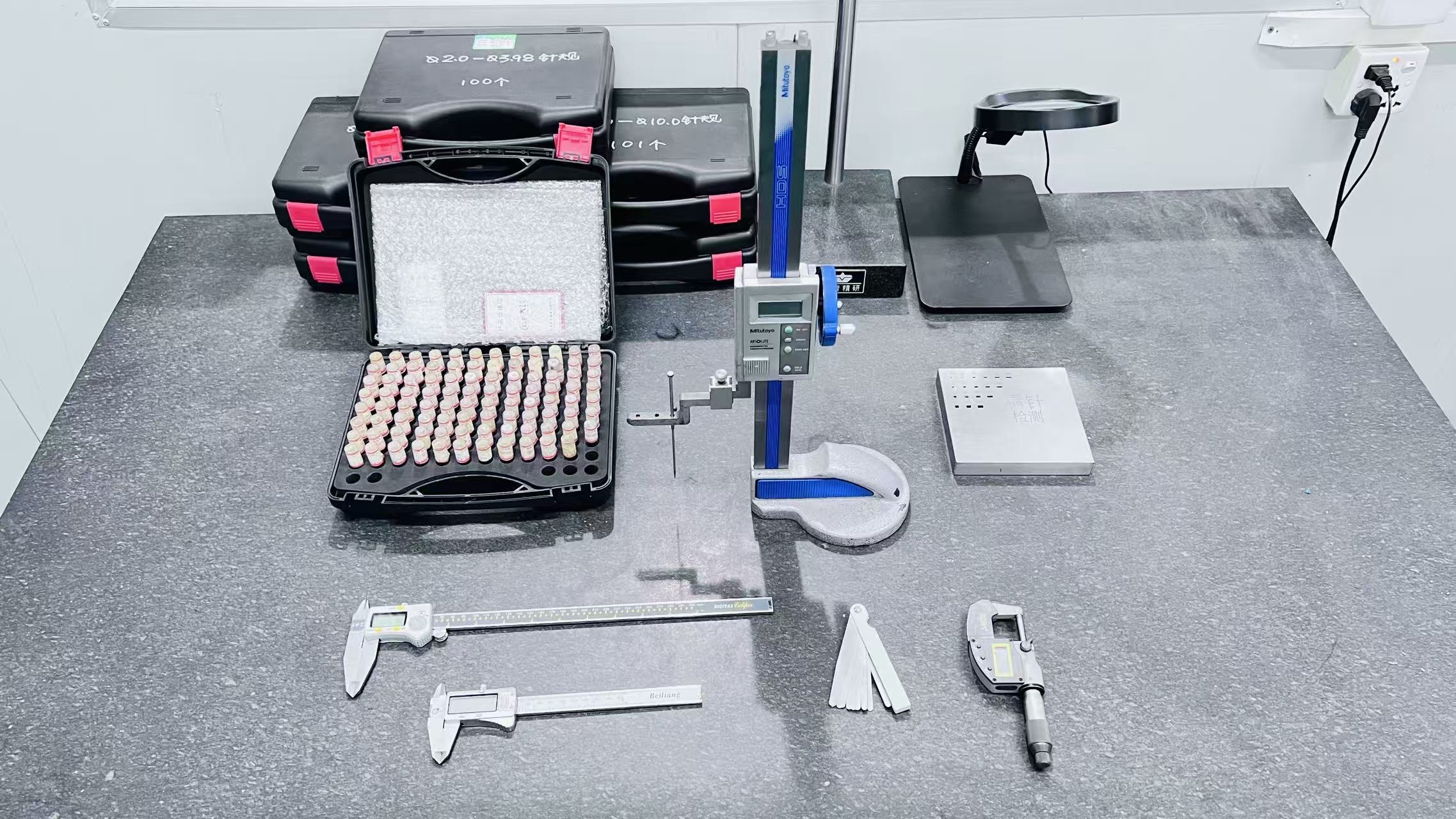
Take the same 106mm PC part. Measured on the shop floor at 28°C rather than in a 20°C inspection room, the reading is biased by roughly 0.05–0.06mm. The CMM in our inspection room is specified to ±0.001mm. Optical comparators are specified to ±0.005mm.
The gauge is roughly 50 times more accurate than the temperature error being ignored. Buying a better CMM does not fix a measurement taken in the wrong room.
Moisture in hygroscopic resins
Polyamides, PBT, and PC absorb water from ambient air. Absorbed moisture acts as a plasticiser: the part swells, and for PA66 in particular the effect is large enough to dominate the tolerance conversation on thick sections. A PA66 part measured dry-as-molded and the same part measured after conditioning at 23°C / 50% RH are not the same size.
This is a specification problem, not a molding problem. The drawing must state the conditioning state in which the tolerance applies — otherwise the molder measures dry, the customer measures conditioned, and both are correct. The standards and the error patterns are covered in our injection molding tolerances guide, and the moisture behaviour of PA66 and PA6 specifically in the nylon molding guide.
What a Constant-Climate Cell Actually Changes
A clean room is usually specified for cleanliness. The dimensional side effect is the one that gets overlooked, and it operates through three separate mechanisms.
1. Molding happens at a stable temperature
Shrinkage is a function of the temperature differential between the melt and the mold cavity. The mold temperature itself is controlled by a chiller or heater circuit — but that circuit is rejecting heat into the room. If the room swings 15°C between a January morning and an August afternoon, the mold temperature control loop is fighting a moving target, and cavity surface temperature moves with it. Shrinkage moves with that.
Molding inside a temperature-controlled cell removes the ambient swing from the equation, so the process window established at first article stays valid across the year.
2. Measurement happens at the reference temperature
Our controlled cell holds 20–24°C ±2°C and 40–60% RH. A CMM or optical comparator operated in that room is measuring at or near the ISO 1 reference, and successive measurements are comparable to each other regardless of the season.
3. Contamination is controlled
This is the part clean room suppliers usually lead with, and it matters for a different reason than dimensional accuracy. Particles on a connector contact, an optical surface, or a fluid path are functional defects. Inside the cell we also keep resin in sealed hoppers on a dedicated dryer, and parts are bagged and sealed within the controlled environment rather than carried across a production floor.
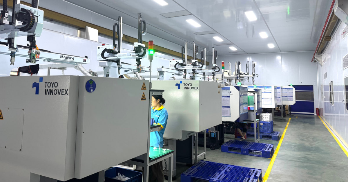
The actual specification of our ISO 8 cell
| Parameter | Specification |
|---|---|
| Cleanliness class | ISO 8 / Class 100,000 (ISO 14644-1) |
| Particle limit ≥0.5µm | 3,520,000 particles/m³ |
| Particle limit ≥5.0µm | 29,300 particles/m³ |
| Filtration | HEPA, 99.97% at 0.3µm |
| Air pressure | Positive — outward flow |
| Temperature | 20–24°C ±2°C |
| Relative humidity | 40–60% RH |
| Air changes | Minimum 20 per hour |
| Monitoring | Particle counter, temperature, RH — logged per shift |
| Presses | Dedicated 90T–250T servo-hydraulic, robot part removal |
| Material handling | Sealed hoppers, dedicated dryer, no shared resin |
| Packaging | Bagged and sealed inside the cell |
The cell is described in more detail on our clean room injection molding service page, including the personnel and gowning protocol.
Which Parts Need This — and Which Do Not
A clean room is not automatically required for tight tolerances, and claiming otherwise would be a sales position rather than an engineering one. The drift table above gives the decision framework: compare the expected environment-induced drift to the tolerance band, and consider it alongside the other variation sources.
| Situation | Environment-induced drift | Practical verdict |
|---|---|---|
| Large unfilled part (>80mm), tolerance ≤±0.1mm | High — can exceed 30% of band | Climate control plus a conditioning spec on the drawing |
| Medical device or implantable, any tolerance | Moderate to high | Controlled cell required for cleanliness regardless of dimension |
| Optical or connector contact surfaces | Low dimensional impact | Controlled cell required for particle control |
| Glass-filled grade, tight tolerance | Low — anisotropy and weld lines dominate | Mold design and gate location matter more than ambient control; stable measurement room still required |
| Amorphous part (PC, ABS) with ±0.15mm or wider | Low | Standard floor is adequate |
| Small features under 10mm | Negligible | Standard floor is adequate |
The honest summary: climate control buys you the removal of one variation source. It is decisive when the drift is a large fraction of the band and the process is already running near its capability limit. It is not a substitute for a capable mold, a stable process, or a correctly toleranced drawing.
What to Put on the Drawing
If the tolerance conversation is going to be about the environment, the drawing has to say so. Five items, all of which are routinely omitted:
1. Reference temperature. State that dimensions apply at 20°C, or state the actual temperature at which the part will be gauged by your incoming inspection.
2. Conditioning state. For PA, PBT, and PC, state whether the tolerance applies dry-as-molded, or after conditioning per ISO 291 (23°C / 50% RH) or ISO 1110. Without this, first article and incoming inspection can legitimately disagree.
3. Measurement method and instrument. CMM versus optical comparator versus contact gauge produce different numbers on the same feature, particularly on soft or thin-walled parts where contact force deflects the part. A CMM at ±0.001mm and a hand gauge at ±0.02mm are not interchangeable.
4. Datum scheme. Tolerances are meaningless without defined datums. On molded parts the practical datum hierarchy is usually a primary locating boss or plane, a secondary locating feature, and the gate witness as a tertiary reference.
5. Which dimensions are functional and which are reference. A drawing that tolerances every dimension equally forces the molder to chase non-functional features and adds cost without adding value. Mark the functional dimensions and let the rest carry the general tolerance.
Dimensions that cannot be held regardless of the room
Three cases where a tighter environment does not help, and where the tolerance should be relaxed or the design changed:
- Across a weld line. Material filling from two directions meets with reduced strength and unpredictable local shrinkage. Any dimension whose measurement path crosses a weld line carries variation that no climate control removes.
- Across the parting line. Mold half alignment, clamp force variation, and flash thickness add variation. Prefer to define critical dimensions within one mold half.
- On free surfaces. Non-datum surfaces with no locating relationship to the tool have no controlled reference, so tight tolerances there are unenforceable.
Frequently Asked Questions
Does precision molding require a clean room?
No. Many precision parts are molded on a standard floor and measured in a temperature-controlled inspection room. A clean room is required when the part also demands contamination control — medical devices, optical surfaces, fluid paths, connector contacts — or when the part is large enough that ambient temperature drift consumes a significant share of the tolerance band.
What temperature should molded parts be measured at?
20°C is the international reference temperature for dimensional metrology (ISO 1). Measuring at 20–24°C keeps thermal bias small relative to typical tolerance bands. If your incoming inspection cannot control temperature, specify the actual inspection temperature on the drawing so the molder and the customer are measuring under the same conditions.
How much does a 10°C temperature change actually move a plastic part?
It depends on the material and the length of the dimension. On a 106mm PC feature, roughly 0.07mm. On the same length in unfilled POM or PP, 0.10–0.19mm. On a 6mm feature, under 0.01mm. The drift is proportional to length, which is why large parts and full-length dimensions are the ones that fail.
Can ±0.02mm be held on an unfilled nylon part?
Not on a large dimension. Unfilled PA66 has a CLTE of roughly 70–100 µm/m·K and absorbs moisture, so a 100mm dimension moves more than 0.02mm from a modest temperature change alone — before process variation is considered. ±0.02mm on unfilled nylon is realistic on small features with a controlled process and a specified conditioning state. On long dimensions, either the material changes to a glass-filled grade or the tolerance is relaxed.
What is the difference between dry-as-molded and conditioned?
Dry-as-molded means the part is measured immediately after molding, before it has absorbed ambient moisture. Conditioned means the part has been held at a defined temperature and humidity until moisture content stabilises — typically 23°C / 50% RH per ISO 291. For PA66 the dimensional difference between the two states can exceed the entire tolerance band on thick sections. The drawing must say which state the tolerance applies to.
Does a clean room improve dimensional accuracy?
Indirectly, and only in specific ways. It removes ambient temperature swings from the molding process, allows measurement at the reference temperature, and keeps resin moisture controlled through dedicated drying. It does not correct a mold that is not capable, a process that is not stable, or a tolerance that the material cannot hold.
How We Handle Precision Parts in the Controlled Cell
Critical dimensions are monitored by SPC every 50–100 shots, with per-cavity Cpk reporting rather than a single part measurement. First article includes a full dimensional report of every drawing dimension, measured on a SEREIN CMM at ±0.001mm with calibration traceable to national standards. Our full inspection workflow is described on the quality page.
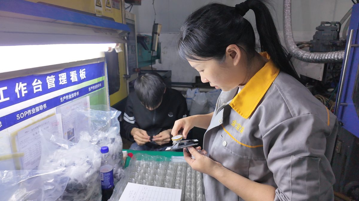
For parts that combine tight tolerances with a cleanliness requirement, production runs in the ISO 8 cell with dedicated servo-hydraulic presses, robot part removal, and sealed packaging inside the controlled environment. The precision injection molding service covers the capability side — tolerances to ±0.02mm with Cpk ≥1.67 on validated features.
Before quoting a precision part we review each toleranced dimension against the material, geometry, wall thickness, gate location, and cooling layout, and we tell you which dimensions are achievable at standard production, which need premium tooling, and which cannot be held by any process. That review is included with every quotation.
Submit your drawing and toleranced dimensions for a DFM review →