Precision Injection Molding — How to Achieve ±0.005mm Tolerances
A procurement engineer at a medical device company sends the same part file to three injection molders. The part is a sensor housing — 45 mm long, ABS/PC, with a bearing bore tolerance of 28.00 ±0.02 mm and a seal groove depth of 1.50 ±0.01 mm. Two suppliers return quotes for standard P20 tooling at similar prices. The third supplier quotes an S136 stainless mold at roughly 40 percent more and asks about coolant temperature control, cavity pressure transducers, and whether the Cpk requirement is 1.33 or 1.67.
The third supplier is quoting precision injection molding. The first two are quoting injection molding. The difference is not marketing — it is tool steel, process control, and measurement capability, and it determines whether the bearing bore is 28.02 mm every time or 28.02 mm most of the time.
This guide explains what separates precision molding from standard molding, how the system works, and what to look for when qualifying a supplier for tight-tolerance parts.
1. What Precision Injection Molding Actually Means
Standard injection molding typically holds ±0.05 mm on well-designed parts in stable materials. Precision injection molding pushes that to ±0.01–0.02 mm — and in some cases to ±0.005 mm on specific features. The distinction is not just a tighter number on a drawing. It is a fundamentally different approach to process control.
In standard molding, the machine injects material into a mold, the part cools, the mold opens, and the part is ejected. Dimensional variation is managed by setting process parameters within a window and accepting the natural variation of the process — typically a Cpk of 1.0–1.33 on non-critical dimensions.
In precision molding, the process is actively controlled to hold dimensional variation below a specified threshold. Cavity pressure sensors monitor the filling and packing phase in real time. Mold temperature is maintained within ±1°C by a closed-loop temperature control unit — not a hose from the mains. Injection velocity is profiled, not set to a single value. The process transfers from velocity control to pressure control at a specific cavity pressure — not at a screw position limit switch. These are not optional upgrades. They are the minimum requirements for holding ±0.02 mm or better over a production run.
The target audience for precision molding is engineers designing parts where dimensional variation directly affects function: bearing bores, seal surfaces, snap-fit engagement, gear tooth profiles, optical alignment features. If your part works fine at ±0.1 mm, you do not need precision molding. If it fails at +0.03 mm, you do.
2. The Four Pillars of Precision Molding
Precision molding capability is not a machine specification. It is a system built from four interdependent elements.
Pillar 1 — Mold Steel
The mold steel determines the thermal stability and wear resistance of the cavity over the production life of the tool. For precision work, the steel grade is not negotiable.
| Steel | Hardness | Thermal Conductivity | Best For |
|---|---|---|---|
| P20 | 28–32 HRC (pre-hardened) | Moderate | General production, tolerances to ±0.05 mm |
| H13 | 48–52 HRC | Lower | High-volume production, filled materials |
| S136 / 420SS | 48–52 HRC | Lower | Corrosion resistance, optical finish, medical |
| NAK80 | 38–42 HRC | Moderate | High-polish, tight tolerance, excellent dimensional stability |
| NAK55 | 38–42 HRC | Moderate | Similar to NAK80 with added machinability |
For precision molding, P20 is rarely the correct choice. P20 moves under sustained thermal cycling — the cavity dimensions shift by microns over thousands of cycles as the steel expands and contracts. A mold running 300°C melt temperature with 20°C coolant undergoes a 280°C temperature swing every cycle. The steel expands with each shot and contracts during cooling. P20, at 28–32 HRC, has lower yield strength than hardened tool steels and will creep — slowly, microscopically, irreversibly — over the tool’s life. For parts toleranced at ±0.05 mm, this movement is within the tolerance band. For parts at ±0.02 mm, it consumes half the available tolerance before the first part is molded.
S136 stainless and NAK80 are the standard choices for precision work. S136 offers corrosion resistance for medical and optical applications. NAK80 offers exceptional dimensional stability with better machinability than S136 — it polishes to SPI A-1 without the porosity that sometimes appears in hardened H13. Both hold cavity geometry over 500,000+ cycles with dimensional drift below 0.005 mm.
Pillar 2 — Temperature Control
Mold temperature is the single largest process variable affecting part dimensions. A 5°C variation in mold surface temperature changes the cooling rate of the polymer, which changes the crystallization behaviour of semi-crystalline resins and the free-volume relaxation of amorphous resins — both of which change the final part dimensions.
Precision molding requires mold temperature control within ±1°C. This is achieved by:
- A dedicated mold temperature controller (TCU) with closed-loop PID control — not tap water through a flow regulator
- Independently controlled cooling circuits for cavity and core — the cavity side typically runs 5–10°C hotter than the core to control warpage direction
- Coolant manifolds with individual circuit flow meters — a partially blocked cooling channel on one side of the cavity produces asymmetric cooling and differential shrinkage across the part
The coolant itself matters. Water is standard. For mold temperatures above 90°C — required for PEEK, PPS, LCP, and other high-temperature engineering resins — pressurized water or oil-based TCUs are required. The TCU must maintain temperature not just at the unit outlet but at the mold surface, which requires adequate coolant flow rate, clean channels, and correctly sized supply lines.
Pillar 3 — Process Control
The injection molding machine for precision work must control the process at a higher resolution than a standard machine.
Closed-loop injection velocity control. A standard machine controls screw position — the screw advances to a set transfer position, and the controller switches to hold pressure. A precision machine controls injection velocity as a profiled curve — velocity at the gate, velocity during fill, velocity at the end of fill — with feedback from the screw position sensor updated every millisecond. The velocity profile is developed during process development and locked as a recipe parameter, not an operator adjustment.
Cavity pressure transfer. The switch from fill to pack is the most sensitive event in the molding cycle. On a standard machine, transfer occurs at a screw position — typically 2–5 mm before the screw reaches the end of its stroke. On a precision machine, transfer occurs at a cavity pressure setpoint measured by a piezoelectric pressure sensor mounted in the mold cavity or runner. When the cavity pressure reaches the setpoint — typically 200–400 bar for engineering resins — the controller switches to pressure control. This eliminates shot-to-shot variation caused by check ring leakage, melt viscosity changes, and screw position sensor drift.
Profiled hold pressure. The hold pressure is not a single value held for a fixed time. It is a profiled curve — high pressure during gate freeze, stepped down as the part solidifies — designed to pack the part to the target weight while minimizing residual stress. The profile is developed from gate freeze studies: the hold time at each pressure step is determined by measuring part weight at progressively longer hold times until the weight stabilizes, indicating the gate has frozen.
Pillar 4 — Measurement and Verification
Precision molding without precision measurement is not precision molding — it is standard molding with tighter numbers on the drawing and no evidence that the parts meet them.
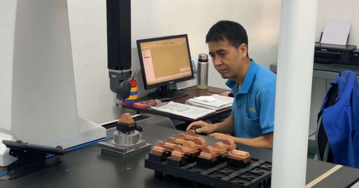
CMM inspection. A coordinate measuring machine with ±0.002 mm volumetric accuracy is the minimum for verifying parts toleranced at ±0.02 mm. The measurement uncertainty of the CMM must be less than 10 percent of the tolerance band — for ±0.02 mm, the CMM must be accurate to ±0.002 mm or better. Zeiss and Hexagon bridge CMMs with scanning probes are the industry standard. Touch-trigger probes on older CMMs introduce point-sampling error on curved surfaces and are not adequate for sub-0.03 mm work.
SPC and process capability. Dimensional data from the CMM is fed into statistical process control software that calculates Cpk for each critical dimension. Cpk measures how well the process is centered within the tolerance band and how much variation exists relative to the tolerance width. A Cpk of 1.33 means the process spread (6 sigma) fits within the tolerance band with some margin. A Cpk of 1.67 — typical for automotive PPAP Level 3 — means the process spread fits within the tolerance band with comfortable margin and the process mean is well-centered. For medical devices, Cpk ≥ 1.67 on critical dimensions is the expected standard.
First article inspection. Every new or modified mold undergoes FAI: a complete dimensional inspection of the first production parts against the 2D drawing, with every dimension reported. The FAI report establishes the baseline. In-process inspection at defined intervals — typically every 2–4 hours during production — verifies that the process has not drifted from the baseline.
3. Material Considerations for Precision Parts
The polymer itself is a source of dimensional variation. Different materials require different precision strategies.
Amorphous resins (ABS, PC, PS, PMMA) shrink predictably and isotropically — 0.4–0.7 percent uniformly in all directions. They are inherently more dimensionally stable than semi-crystalline resins and are preferred for precision parts where the application allows their use.
Semi-crystalline resins (PA, POM, PBT, PEEK, PPS) shrink anisotropically — more in the flow direction than transverse to flow, and the ratio depends on the degree of crystallinity, which depends on the cooling rate. A PA66 part cooled slowly in a hot mold crystallizes more and shrinks differently than the same part cooled quickly in a cold mold. This makes semi-crystalline resins significantly harder to mold to tight tolerances — the process window that produces acceptable dimensions is narrower, and the mold temperature must be controlled within ±1°C to achieve consistent crystallinity.
Filled materials. Glass fiber and mineral fillers reduce shrinkage and improve dimensional stability — PA66-GF30 shrinks 0.2–0.5 percent versus 1.0–2.0 percent for unfilled PA66 — but they introduce anisotropy: shrinkage in the flow direction can be half the shrinkage transverse to flow. The fiber orientation, which depends on gate location and part geometry, determines the local shrinkage behaviour. Precision parts in filled materials require mold flow simulation to predict fill pattern and fiber orientation before gate location is finalized.
4. DFM for Precision Injection Molding
Designing for precision molding requires attention to features that would be non-critical in standard molding.
Wall thickness uniformity. Differential shrinkage between thick and thin sections is the largest source of warpage and dimensional variation in precision parts. A 3.0 mm wall next to a 1.5 mm wall will cool at different rates, shrink differently, and pull the part out of tolerance. Target uniform nominal wall thickness. Where thickness transitions are unavoidable, make them gradual — a 30-degree ramp, not a step.
Gate location and size. The gate determines the fill pattern and the fiber orientation in filled materials. A gate placed at one end of a long, narrow part produces a linear fill pattern with high anisotropy — different shrinkage along and across the part. A gate placed at the center produces a radial fill pattern with more uniform shrinkage. For precision parts, gate location should be determined by mold flow simulation, not by convenience.
Draft angles. Precision parts still need draft. Zero-draft sidewalls are possible with additional mold complexity (collapsible cores, expanding cavities) but add cost and lead time. A 0.5-degree draft angle on a 20 mm deep feature is the practical minimum for precision ejection without part distortion. Polished cavity surfaces — SPI A-1 or A-2 — allow shallower draft angles than textured surfaces.
Datum structure. The part drawing must define the datum reference frame — the three orthogonal planes from which all dimensions are measured. This is standard practice in machined-part drawings but is often omitted from molded-part drawings. For precision molding, the datum structure tells the mold maker which features control the part’s function and how to set up the CMM inspection program. Without it, the mold maker and the inspector may be measuring the same dimension from different reference surfaces.
5. The Cost of Precision
Precision molding costs more than standard molding. Understanding where the cost comes from — and when it is justified — is part of the procurement decision.
| Cost Driver | Standard Molding | Precision Molding | Premium |
|---|---|---|---|
| Mold steel | P20 | S136 / NAK80 | +40–80% on tooling cost |
| Mold temperature control | Mains water, ±5°C | Closed-loop TCU, ±1°C | +$5–15/hour machine rate |
| Cavity pressure sensing | Not used | Piezoelectric sensors + controller | +$3,000–8,000 per mold |
| Process development | 4–8 hours | 16–40 hours (gate freeze, DOE, Cpk study) | +1–3 days lead time |
| Inspection | Spot-check with calipers/micrometer | CMM inspection, SPC, Cpk reporting | +$200–500 per inspection report |
| Per-part cost | Baseline | +15–30% | Cycle time may be longer, scrap rate lower |
The premium is real. So is the cost of not specifying precision when the part requires it. A medical device that fails a dimensional audit during FDA submission review, an automotive sensor that drifts out of calibration because the housing distorted, a connector that intermittently fails because the pitch between contacts varied by 0.03 mm — these failures cost orders of magnitude more than the precision molding premium.
The decision framework: if dimensional variation directly affects part function, safety, or regulatory compliance, pay for precision. If it affects only appearance or fit of non-critical mating parts, standard molding with realistic tolerances is the more cost-effective choice.
Frequently Asked Questions
What is the tightest tolerance achievable in injection molding?
±0.005 mm is achievable on specific features — typically diameters, bore depths, and short linear dimensions — with an optimized precision molding system. This requires S136 or NAK80 mold steel, ±1°C mold temperature control, cavity pressure transfer, and CMM verification. It is not achievable on every feature of every part, and it should only be specified where the part function requires it. Specifying ±0.005 mm on a non-functional cosmetic surface adds cost with no engineering benefit.
How do I know if my part needs precision molding?
Three questions: (1) Does dimensional variation at ±0.05 mm cause the part to not function? (2) Is the tolerance on a feature that affects safety or regulatory compliance? (3) Does the part mate with another precision component where the interface tolerance determines system performance? If the answer to any of these is yes, precision molding is warranted. If not, standard molding at ±0.05 mm will produce functional parts at lower cost.
Does precision molding require a specific type of injection molding machine?
An all-electric machine is preferred for precision work because it offers higher injection velocity control resolution, better repeatability on screw position, and no hydraulic oil temperature drift — all of which reduce shot-to-shot variation. A well-maintained servo-hydraulic machine can also achieve precision results if equipped with closed-loop control and cavity pressure transfer capability. The machine matters less than the mold steel, temperature control, and process development — a precision mold in a standard machine will outperform a standard mold in a precision machine.
What is the difference between precision molding and scientific molding?
Scientific molding is the process development methodology — establishing the injection velocity profile, determining gate freeze time, mapping the process window, and validating with Cpk data. Precision molding is the capability — delivering parts within a tight tolerance band over a production run. You can do scientific molding on a standard part to optimize cycle time and reduce scrap. You cannot do precision molding without scientific molding as the foundation. For more detail, see our guide on Scientific Molding & Process Validation — IQ/OQ/PQ.
Precision injection molding is a system, not a setting. The mold steel, temperature control, process parameters, and measurement verification must all be specified, implemented, and maintained as a coherent whole. The result is parts that meet their dimensional requirements — not most of the time, not when the operator is watching, but over the full production life of the tool. For the medical and electronics engineers who rely on those dimensions, that is the difference between a qualified supplier and an expensive problem.
Submit your part file for a free DFM review and precision molding assessment →
Learn more about JBRplas precision injection molding capabilities →