POM (Acetal/Delrin) Injection Molding Design Guide — Gears, Bearings, and Sliding Parts
A mechanical design engineer is specifying the material for a gear train in a professional-grade cordless drill. The gears are 18–45 mm in diameter, module 1.0, with a 6 mm bore that must maintain a running clearance of 0.05–0.08 mm on a steel shaft after molding and throughout the product’s service life. The gear train transmits 80 N·m peak torque at 1,800 RPM with grease lubrication at an operating temperature of 60–80°C. The material shortlist has two entries: PA66 and POM. The wrong choice produces gears that seize when the ambient humidity drops from 60% to 20% — or that strip teeth because the material was not designed for cyclic tooth-root bending loads.
A different engineer — at an automotive fuel system supplier — is designing a fuel pump impeller that runs submerged in gasoline at 60°C. The impeller must maintain 0.03 mm tip clearance on the housing wall, resist swelling and dimensional change after 5,000 hours of fuel immersion, and survive 100,000 start-stop cycles. ABS and PC are eliminated immediately — neither survives gasoline immersion. Nylon swells by 0.5–0.8% from moisture alone — in gasoline with 10% ethanol, the dimensional change is unpredictable. POM is the answer — not because it is the strongest material, but because it is the most dimensionally stable in this environment.
POM (polyoxymethylene), sold under trade names including Delrin (DuPont) and Hostaform (Celanese), is the material that engineers specify when a part must slide, wear, or maintain a precision fit — and when nylon’s moisture-driven dimensional change is disqualifying. It is the standard material for gears, bearings, cams, valve bodies, pump components, and any application where low friction, wear resistance, and dimensional stability in service matter more than absolute tensile strength.
What POM Is — Homopolymer vs Copolymer
POM is a semicrystalline engineering thermoplastic with a simple molecular structure: a repeating –(CH₂–O)– backbone. The formaldehyde-based chemistry produces a polymer with exceptionally high crystallinity (typically 70–80%), which directly produces its defining characteristics: high stiffness, low friction, excellent fatigue resistance, and low moisture absorption.
Two families are commercially available, and the difference matters for mold design and processing:
| Property | POM Homopolymer (Delrin) | POM Copolymer (Hostaform) |
|---|---|---|
| Crystallinity | 75–85% | 70–75% |
| Melting point | 175–180°C | 165–170°C |
| Tensile strength (yield) | 68–72 MPa | 60–65 MPa |
| Flexural modulus | 2.8–3.2 GPa | 2.5–2.8 GPa |
| Notched Izod impact | 6–8 kJ/m² | 5–7 kJ/m² |
| Continuous use temp | 90–100°C | 85–95°C |
| Mold shrinkage | 1.8–2.2% | 1.8–2.2% |
| Thermal stability (processing) | Narrower window — degrades above 190°C | Wider window — stable to 200°C |
| Centerline porosity risk | Higher (rapid crystallization) | Lower |
| Chemical resistance | Less resistant to hot water and bases | More resistant to hot water and bases |
| Relative price ($/kg) | $3.50–5.00 | $3.00–4.50 |
The homopolymer (Delrin) offers slightly higher mechanical properties — roughly 10–15% higher tensile strength and modulus — and is preferred for mechanical components where those properties translate directly to thinner gear tooth sections or higher load capacity.
The copolymer (Hostaform) offers a wider processing window — the comonomer units interrupt the POM chain and make it more thermally stable, reducing formaldehyde generation during processing. It also has better resistance to hot water and alkaline environments, which matters for plumbing, dishwasher, and washing machine components.
The practical selection rule: Choose homopolymer for gears, bearings, and mechanical components where the 10–15% mechanical property advantage is used. Choose copolymer when the part will be exposed to hot water, alkaline cleaning agents, or when the processing window is tight — multi-cavity tools with long runner systems, hot-runner molds, or parts with thick sections that result in longer cycle times. The copolymer forgives longer residence time; the homopolymer does not.
Key Properties — Why Engineers Specify POM
Low Friction and Self-Lubrication
POM’s coefficient of friction against steel is 0.2–0.3 dry and 0.05–0.10 lubricated — among the lowest of any unfilled engineering thermoplastic. This is not a coating or additive effect — it is inherent to the material’s surface chemistry and high crystallinity, which produces a smooth, hard surface at the molecular level.
The practical result: a gear molded in POM running against a steel pinion or another POM gear operates quietly, with low wear, and does not require external lubrication for light to moderate loads. This eliminates a grease fitting, a lubricant reservoir, or a periodic maintenance step from the product design.
POM’s low friction is why it is the default material for:
- Gears, racks, and pinions in printers, copiers, and office equipment
- Bearing cages and thrust washers in automotive transmissions
- Sliding elements in furniture hinges, drawer slides, and window mechanisms
- Cams and levers in consumer appliances
- Conveyor belt chain links in food processing equipment (FDA grades available)
Dimensional Stability — The Nylon Differentiator
POM absorbs 0.2–0.3% moisture at equilibrium at 50% RH. Nylon PA66 absorbs 1.5–2.5%. This 10× difference is the single most important reason to choose POM over nylon.
A gear molded in nylon with a 6.00 mm bore at dry-as-molded conditions will have a 6.03–6.05 mm bore after moisture conditioning. The running clearance on the shaft changes, and in a tightly toleranced gear train, the backlash changes with it. A gear molded in POM with the same 6.00 mm bore will have a 6.01–6.02 mm bore after equilibration — the dimensional change is negligible in most designs.
The scenarios where POM wins over nylon on dimensional stability:
- Precision gears and bearings where running clearances are 0.03–0.08 mm
- Parts used in environments with wide humidity variation (outdoor, unconditioned spaces)
- Parts that cannot be moisture-conditioned before assembly (supply chain or cost constraints)
- Parts where post-molding dimensional change would affect assembly fit or function
High Stiffness and Fatigue Resistance
POM’s flexural modulus of 2.5–3.2 GPa is 10–15% higher than unfilled nylon (2.6–3.0 GPa) and comparable to unfilled PC (2.2–2.5 GPa). But modulus alone undersells the material — POM’s advantage is fatigue resistance under cyclic loading.
Gear teeth experience cyclic bending stress at every tooth engagement — a 20-tooth gear at 1,800 RPM sees 36,000 tooth-loading cycles per minute. Over a 500-hour product life, the tooth root sees over one billion stress cycles. Unfilled nylon under this regime will eventually fail by fatigue crack initiation at the tooth root — the amorphous regions between crystalline domains accumulate damage over millions of cycles until a microcrack forms and propagates.
POM’s exceptionally high crystallinity (70–80%) means there is very little amorphous material to accumulate fatigue damage. The crystalline domains resist cyclic loading more effectively, giving POM a fatigue endurance limit that is higher than unfilled nylon and competitive with glass-filled grades — without the abrasiveness that glass fibre brings to mold steel.
Chemical Resistance
POM resists most organic solvents, oils, greases, fuels, and neutral chemicals. It is the standard material for fuel system components, chemical metering pump parts, and aerosol valve bodies for this reason.
POM’s chemical vulnerabilities are specific and important to know:
- Strong acids (pH below 4) attack the acetal linkages, causing surface etching and eventual embrittlement. Concentrated hydrochloric, sulfuric, and nitric acids will destroy POM parts.
- Strong bases (pH above 10) attack POM homopolymer more aggressively than copolymer. Hot sodium hydroxide solution will etch and embrittle homopolymer POM within hours.
- Hot water above 80°C — POM is not hydrolytically stable in hot water over extended periods. The acetal linkages hydrolyze, reducing molecular weight and embrittling the part. For hot-water applications, copolymer POM is preferred over homopolymer, and PPS or PSU should be considered for continuous exposure above 80°C.
- Chlorine and oxidizing agents — bleach (sodium hypochlorite), hydrogen peroxide, and other strong oxidizers attack POM. Dishwasher components, for example, must survive alkaline detergents and 70°C water — copolymer POM is borderline acceptable; reinforced PP or PPS is safer.
Processing POM — Parameters That Matter
Drying
POM absorbs little moisture and is less hygroscopic than nylon or PC. However, drying is still required — not to remove water, but because surface moisture on pellets can create steam splay and because moisture accelerates formaldehyde generation during processing.
| Parameter | POM Homopolymer | POM Copolymer |
|---|---|---|
| Drying temperature | 80–90°C | 80–90°C |
| Drying time | 2–4 hours | 2–4 hours |
| Maximum moisture | <0.10% | <0.10% |
| Drying method | Desiccant or hot-air hopper dryer | Desiccant or hot-air hopper dryer |
POM’s drying requirements are less demanding than nylon (4–6 hours at 80°C to reach <0.15%) or PC (3–4 hours at 120°C to reach <0.02%). A hot-air hopper dryer is adequate for POM in most production environments, though a desiccant dryer provides margin in high-humidity conditions.
Barrel Temperature — The Degradation Window
This is the most important processing parameter for POM. The material processes at 180–210°C — but degrades rapidly above 210°C with formaldehyde gas generation. The window between “hot enough to melt” and “hot enough to degrade” is 20–30°C, which is narrower than nylon (40–50°C) or ABS (60–80°C).
| Zone | POM Homopolymer | POM Copolymer |
|---|---|---|
| Feed (rear) | 170–180°C | 165–175°C |
| Compression | 180–195°C | 175–190°C |
| Metering (front) | 190–205°C | 185–200°C |
| Nozzle | 190–205°C | 185–200°C |
The degradation risk is real: if the melt temperature exceeds 210°C for more than a few minutes, the POM backbone begins to unzip — formaldehyde (CH₂O) gas is released, and the polymer molecular weight drops. The formaldehyde is immediately detectable by its pungent, irritating odor. A processing environment that smells strongly of formaldehyde indicates that the material is degrading and the barrel temperature or residence time must be reduced.
Critical processing rules for POM:
Minimize residence time. At 200°C, POM can tolerate 10–15 minutes of residence time. At 210°C, the safe residence time drops to 5–8 minutes. Size the shot weight so that the barrel residence time is under 5 minutes — POM should never sit in a hot barrel waiting for the next shot.
Purge before shutdown. Never leave POM in a hot barrel during a production stoppage. Purge the barrel with LDPE, PP, or a commercial purging compound before shutting down. POM left in a barrel at 180–200°C for an extended shutdown will degrade, release formaldehyde, and produce corrosive formic acid as a secondary decomposition product — which can pit the barrel and screw surfaces.
Adequate barrel ventilation. The area around the machine nozzle and mold parting line should be ventilated — not because POM processing is hazardous (the formaldehyde levels from normal processing are well below occupational exposure limits), but because the odor is unpleasant and a sensitive indicator of process problems. An increase in formaldehyde odor during a production run signals that the melt temperature is climbing or the residence time is too long.
Mold Temperature
POM mold temperature controls crystallinity, shrinkage, and surface finish:
| Application | Recommended Mold Temp | Why |
|---|---|---|
| Precision gears (tight tolerance) | 90–110°C | Maximum crystallinity, lowest post-mold shrinkage |
| General mechanical parts | 70–90°C | Good crystallinity, controlled shrinkage |
| Cosmetic parts (no dimensional criticality) | 60–80°C | Adequate surface, faster cycle |
A mold temperature below 60°C produces a POM part with low crystallinity at the surface layer — the melt in contact with the cold mold wall freezes before the polymer chains can organize into crystalline domains. This amorphous skin layer is 0.05–0.2 mm thick and has different density, shrinkage behavior, and wear resistance than the crystalline core.
For precision gears where post-molding dimensional change must be minimized, mold temperature of 90–100°C is standard — it produces near-equilibrium crystallinity in the molded part, minimizing the dimensional change that would otherwise occur as the part slowly approaches equilibrium crystallinity at room temperature over days to weeks.
Injection Speed and Holding Pressure
POM has lower melt viscosity than PC or glass-filled nylon. It flows easily — gates of 0.8–1.5 mm diameter are typically adequate for unfilled POM. This low viscosity has two processing consequences:
Fast injection is standard. POM’s low melt viscosity and rapid crystallization produce a material that fills quickly and solidifies quickly. Fill times of 0.5–1.5 seconds are typical, and hesitation at wall thickness transitions is less common than with higher-viscosity materials.
Holding pressure is critical for sink mark control. POM’s high mold shrinkage (1.8–2.2%) means the holding pressure must pack enough additional material into the cavity to compensate for the density increase during crystallization. Inadequate holding pressure produces sink marks at thick sections, voids in the center of thick ribs, and dimensional variation. Holding pressure for POM is typically 60–80% of injection pressure, maintained until the gate freezes.
Avoiding Centerline Porosity
POM homopolymer is susceptible to centerline porosity — microscopic voids along the centerline of thick sections (typically >4 mm) caused by the volumetric shrinkage during crystallization pulling material away from the center faster than the holding pressure can replenish it. The voids are typically 0.05–0.3 mm in diameter and reduce the effective cross-section of the part.
Solutions: use POM copolymer (lower and more controlled crystallization shrinkage), increase gate size and holding pressure, or redesign the part to avoid sections thicker than 4 mm. If a thick section is unavoidable, a mold flow analysis with shrinkage prediction can identify the void locations and inform gate repositioning or holding pressure optimization.
Mold Design for POM
Shrinkage and Cavity Dimensions
POM’s mold shrinkage of 1.8–2.2% is high — roughly 3–4× higher than ABS (0.4–0.7%) and comparable to unfilled nylon (1.2–1.8%). The cavity must be cut larger than the part drawing dimensions by this amount, and the shrinkage is anisotropic — it varies with flow direction (higher in the flow direction due to molecular orientation during filling), wall thickness (higher in thick sections), and mold temperature (higher at higher mold temperature due to increased crystallinity).
For precision gears where tooth profile accuracy is critical, a single uniform shrinkage factor applied to the entire cavity is rarely adequate. The cavity should be cut based on mold flow analysis with shrinkage prediction, and the gear tooth profile should be verified on T1 samples and adjusted if necessary.
Gating
POM’s low melt viscosity means it flows through small gates easily. However, gate location determines the molecular and crystalline orientation field in the part — and for POM, this directly affects mechanical properties and dimensional stability.
Gate location rules for POM gears:
- Gate into the gear hub or web, not into the teeth. A gate on the tooth flank produces orientation through the tooth that makes it weaker at the root — exactly where bending stress is highest.
- Use a diaphragm gate or three-point pin gate at the hub for gears under 60 mm diameter. This produces radial flow from the center outward, orienting polymer chains along the tooth radial direction — the direction of bending stress.
- For gears over 60 mm, a ring gate or multiple pin gates at the hub provide balanced filling without creating weld lines in the toothed rim.
General gate design for POM:
- Submarine (tunnel) gates work well — POM’s stiffness at ejection temperature allows clean separation at the gate.
- Tab gates are preferred for thick sections where a direct gate would create a long cooling time at the gate area.
- Hot-runner systems for POM must be designed for the narrow processing window — the hot-runner manifold temperature must stay below 210°C to avoid material degradation. POM copolymer is preferred over homopolymer for hot-runner molds.
Venting
POM generates formaldehyde gas during processing — even under normal conditions with correct barrel temperature. The gas must be vented from the cavity; otherwise, it compresses at the last point to fill, producing burn marks (actually thermal degradation marks from the diesel effect — the formaldehyde-air mixture ignites under compression).
Vent depth of 0.015–0.02 mm and width of 3–6 mm at the last point to fill is standard for POM. Additional venting at weld line locations is recommended — the gas carried to the weld line by the converging flow fronts can become trapped, weakening the weld line and producing surface defects.
Ejection
POM is stiff at ejection temperature and has a higher coefficient of thermal expansion than steel — it grips the core tightly during cooling. Ejector pins must provide sufficient area to avoid puncturing the part surface, and draft angles should be ≥1° on the core side for parts deeper than 20 mm.
POM’s surface hardness and low friction make it less prone to scuffing during ejection than softer materials like PP. This is an advantage — the ejector pin marks are typically minimal, and the part releases cleanly if draft angles and ejection forces are correctly designed.
POM vs Nylon vs PBT — Quick Selection for Sliding and Mechanical Parts
When an engineer is choosing between POM, nylon, and PBT for a mechanical component, the decision usually hinges on one or two requirements:
| Criterion | POM | PA66 (Nylon) | PBT |
|---|---|---|---|
| Coefficient of friction (dry vs steel) | 0.2–0.3 | 0.2–0.3 | 0.25–0.35 |
| Wear resistance | Excellent | Good | Fair |
| Tensile strength | 68–72 MPa | 80–85 MPa | 55–60 MPa |
| Stiffness | 2.8–3.2 GPa | 2.8–3.0 GPa | 2.3–2.5 GPa |
| Impact (conditioned) | 6–8 kJ/m² | 8–15 kJ/m² | 3–5 kJ/m² |
| Moisture absorption (24h) | 0.2–0.3% | 1.2–1.6% | 0.1% |
| Dimensional change (DAM to EMC) | ~0.1% | 0.5–0.8% | <0.05% |
| Fatigue resistance | Excellent | Good | Fair |
| Chemical resistance | Good (except acids, bases) | Good (except acids) | Excellent |
| Mold shrinkage | 1.8–2.2% | 1.2–1.8% | 1.5–2.0% |
| Processing window | Narrow (20–30°C) | Moderate (40–50°C) | Wide (50–70°C) |
Choose POM when the part must maintain precision dimensions regardless of humidity, when low friction and wear resistance are primary requirements, or when the part operates in fuel, oil, or solvent environments. Typical POM applications: gears, bearings, cams, fuel system components, aerosol valves, zippers.
Choose nylon when the part needs higher impact resistance (especially conditioned nylon at 8–15 kJ/m² vs POM at 6–8 kJ/m²), higher thermal capability (PA66 at 100–120°C continuous vs POM at 90–100°C), or lower cost per kilogram. Typical nylon applications: structural brackets, automotive under-hood components, power tool housings.
Choose PBT when the part needs electrical insulation properties, maximum dimensional stability (0.1% moisture absorption), or resistance to automotive fluids at higher temperatures than POM can handle. Typical PBT applications: electrical connectors, sensor housings, relay components.
POM Part Design — Rules That Prevent Failure
Wall Thickness
Uniform wall thickness is more important for POM than for amorphous materials like ABS — the semicrystalline nature means thicker sections cool more slowly, crystallize to a higher degree, and shrink more. A wall thickness transition from 2 mm to 4 mm produces a differential shrinkage of 0.2–0.4% across the transition, creating internal stress and potential warpage.
Design target: 2.0–3.5 mm nominal wall for most mechanical parts. Minimum 1.0 mm for small gears and thin sections (POM’s low melt viscosity fills thin walls well). Maximum 4.0 mm — sections above 4 mm risk centerline porosity in homopolymer and extended cycle time in both grades.
Radii and Corners
POM is notch-sensitive — a sharp internal corner concentrates stress and initiates fatigue cracks under cyclic loading. This is particularly important for gear tooth roots, where the bending stress is highest and the stress concentration from the root radius directly determines the gear’s fatigue life.
Minimum internal corner radius: 0.5 mm for static applications, 1.0 mm for cyclic loading (gears, springs, snap-fit flexures). The root radius of a POM gear tooth should be as large as the tooth geometry permits — every 0.1 mm increase in root radius translates to a measurable improvement in fatigue life under cyclic tooth loading.
Snap-Fits and Living Hinges
POM can be used for snap-fits and living hinges — though it is less forgiving than PP for hinges and less impact-tolerant than nylon for snap-fits. The design rules:
- Snap-fit deflection should be limited to 1.5–2.0% strain at the beam root (vs 2.5–3.5% for nylon). POM’s lower elongation at yield (8–12% vs nylon’s 15–25%) means less deflection before permanent set.
- Living hinges in POM are possible but should use copolymer and benefit from post-molding flex-cycling (flex the hinge 5–10 times to orient the polymer chains at the hinge line before putting the part into service). POM living hinges have a shorter flex life than PP — design for 5,000–10,000 cycles maximum vs 100,000+ for PP.
Applications
Gears
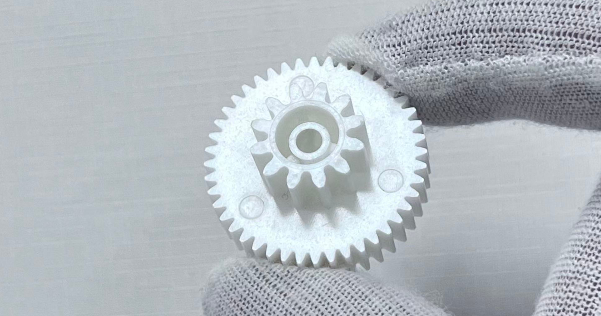
POM is the material behind most injection-molded gears in consumer products, office equipment, and automotive actuators. A POM spur gear in a printer paper feed mechanism runs at 200–500 RPM against a steel pinion, with grease lubrication, for 200,000–500,000 pages — roughly 50–100 million tooth-loading cycles. The material’s fatigue resistance, low friction, and dimensional stability make this possible in a part that costs $0.05–0.20 to mold.
Gear design considerations specific to POM:
- Tooth profile: use a standard involute profile with tip relief to reduce the impact at the start of tooth engagement. POM gears are typically hobbed or shaped after molding only when AGMA Q8–Q10 accuracy is required; AGMA Q5–Q7 accuracy is achievable as-molded with a correctly designed cavity.
- Hub design: the hub should be 2.0–2.5× the bore diameter in outer diameter and 1.5–2.0× the bore diameter in length. A steel shaft running in a POM bore creates a bearing — the POM hub acts as both the gear hub and the journal bearing, eliminating a separate bearing component.
- Thermal expansion: POM’s coefficient of linear thermal expansion of 1.0–1.2 × 10⁻⁴ /°C is roughly 10× higher than steel. A gear with a 6.00 mm bore at 23°C will have a 6.03–6.04 mm bore at 80°C. The running clearance at room temperature must account for this differential expansion to avoid seizure at operating temperature.
Bearings and Bushings
POM plain bearings operate at PV values (pressure × velocity) up to 0.1–0.2 MPa·m/s dry and 0.3–0.5 MPa·m/s with grease lubrication. The bearing wall thickness should be 2.0–3.0 mm — thick enough to handle the radial load distribution, thin enough to maintain dimensional stability and avoid centerline porosity.
For high-PV applications, internally lubricated POM grades containing PTFE, silicone oil, or MoS₂ reduce the coefficient of friction to 0.10–0.15 dry and extend the PV limit to 0.3–0.5 MPa·m/s.
Fluid-Handling Components
POM’s resistance to fuels, oils, and most organic solvents makes it the material of choice for fuel pump impellers, carburetor floats, aerosol valve bodies, and chemical metering pump components. For these applications, POM copolymer is preferred — its better resistance to hot water and alkaline environments provides margin against fuel contaminants, water in the fuel system, and cleaning procedures.
Quality Control
- MFR (Melt Flow Rate) check — POM’s MFR is a sensitive indicator of degradation. A higher-than-specified MFR means the molecular weight has been reduced during processing — the part will have lower tensile strength and fatigue resistance than the specification. MFR should be checked on incoming material and on molded parts from each production lot.
- Dimensional check after 48-hour equilibration — POM parts continue to shrink slightly after molding as the crystalline structure approaches equilibrium. Critical dimensions should be measured after 48 hours at 23°C to verify that the part meets drawing tolerances in its equilibrated state, not just fresh from the mold.
- Gear tooth profile — for precision gears, tooth profile measurement on a gear tester (double-flank or single-flank rolling test) verifies that the molded tooth form meets the accuracy grade. T1 samples should be checked and cavity adjustments made before production release.
- Formaldehyde odor monitoring — during processing, an increase in formaldehyde odor is the earliest warning of melt temperature excursion or excessive residence time. A formalized process for responding to odor change — checking and adjusting barrel temperature, reducing residence time — is more effective than relying on post-molding QC to catch degraded parts.
POM is not the strongest engineering plastic, nor the most impact-resistant, nor the cheapest. It is specified because it does one set of things that no other unfilled thermoplastic does as well: maintain precision dimensions regardless of humidity, resist wear under sliding contact, survive billions of fatigue cycles in gear teeth, and operate reliably in fuels and solvents that destroy other plastics.
A gear molded in nylon works perfectly at 50% RH and seizes when the humidity drops to 15%. A gear molded in POM works the same at both conditions. That is why POM exists.