Overmolding and Insert Molding — A Technical Guide for Product Designers
A well-designed overmolded part looks like a single piece of plastic with two colours and two textures — a rigid black housing with a soft grey grip, a clear lens fused into an opaque frame, a rubber seal permanently bonded around the perimeter. It feels like one part because it is one part — permanently joined at the molecular level during the molding process.
A poorly designed overmolded part looks the same on day one. On day 90, the grip peels off. The seal delaminates. The lens leaks.
The difference is in the material pair, the process choice, and the bond design — decisions made before the first piece of steel is cut. This guide covers what product designers need to know to get overmolding right.
Two Processes, One Goal
Overmolding and insert molding are both methods of combining two materials into a single finished part during the molding process. The distinction is what you are combining:
- Overmolding — molding a second plastic material over a previously molded plastic substrate. The substrate is a molded part. The overmold is an additional plastic layer.
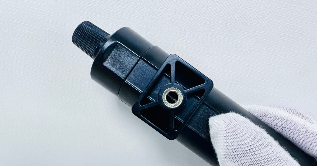
- Insert molding — molding plastic around a non-plastic component — typically a metal insert (threaded bushing, electrical contact, reinforcement pin) — that is placed into the mold before injection.
Both processes eliminate a secondary assembly step. Instead of molding two parts and gluing, welding, or snapping them together, the bond is formed in the mold — stronger, cleaner, and at lower per-unit cost for production volumes.
Three Ways to Overmold
There are three distinct manufacturing methods, and they have very different cost structures.
Method 1: Insert-Overmold (Two-Step Molding)
The substrate is molded on one press as a standard injection-molded part. The substrate is then manually or robotically placed into a second mold — the overmold tool — and the second material is injected over it.
| Attribute | Insert-Overmold |
|---|---|
| Tooling cost | Two single-cavity molds: substrate mold + overmold mold |
| Press requirements | Two standard presses (or one press running both molds sequentially) |
| Cycle time | Two full molding cycles (substrate + overmold) |
| Labour | Part transfer between molds — manual or robot |
| Best for | Volumes under 100,000 parts/year; programs where substrate and overmold use very different process temperatures |
| Tooling cost range | $6,000–$20,000 for both molds combined |
Method 2: 2K Rotary (Two-Shot Molding)
A specialized injection press with two injection units and a rotating mold. The substrate is injected in the first station, the mold rotates 180°, and the overmold material is injected in the second station — all within a single machine cycle. No part handling between shots.
| Attribute | 2K Rotary |
|---|---|
| Tooling cost | One dedicated 2K rotary mold with two sets of cavities |
| Press requirements | Dedicated 2K press with dual injection units |
| Cycle time | Single combined cycle — substrate and overmold molded simultaneously |
| Labour | Fully automated — no manual part transfer |
| Best for | Volumes above 100,000 parts/year; high-volume consumer and automotive programs |
| Tooling cost range | $25,000–$60,000+ |
Method 3: Multi-Step Transfer
The substrate is molded on one press and transferred to a second press for overmolding — similar to insert-overmold but typically with automated handling and dedicated press allocation. Used for programs where volume justifies automation but not a full 2K rotary investment.
Decision rule: If your annual volume is under 100,000 parts, insert-overmold is almost always the correct process choice. If your volume exceeds 500,000 parts, the cycle time and labour savings of a 2K rotary tool dominate the tooling cost difference. The 100,000–500,000 range requires a specific cost analysis for your part geometry and material pair.
Material Compatibility: The Bond Decides
The most important decision in overmolding is the material pair. Not all plastics bond to each other. Some bond chemically — the molecular chains of the two materials interdiffuse at the interface during molding, creating a bond as strong as the base material. Some bond mechanically — the overmold material flows into undercuts, holes, or textured surfaces in the substrate and locks in place mechanically upon cooling. Some do not bond at all — the two materials are chemically incompatible and will delaminate regardless of process parameters.
Chemical Bonding
Chemical bonding occurs when the overmold material is chemically similar to the substrate — typically, a TPE (thermoplastic elastomer) overmolding onto a compatible rigid substrate. The key mechanism is interdiffusion: the molten overmold material softens the surface of the substrate, and polymer chains from both materials entangle at the interface.
Chemical bonding requires:
- The overmold melt temperature to exceed the substrate’s softening temperature at the interface
- Chemical compatibility between the two polymer families
- Sufficient injection pressure to force the overmold material into intimate contact with the substrate
Mechanical Bonding
When chemical bonding is not possible — typically when molding dissimilar polymer families — mechanical bonding is the alternative. The substrate is designed with features that the overmold material flows into: holes, undercuts, channels, or textured surfaces. When the overmold material solidifies, it is physically locked in place.
Mechanical bonding requires:
- Designed-in retention features on the substrate
- Sufficient overmold thickness to resist peel forces
- Attention to thermal expansion mismatch — if the two materials expand at different rates under heat, the mechanical lock can loosen over time
Compatibility Matrix
| Substrate | TPE-S (SEBS) | TPE-V (PP/EPDM) | TPU | TPC (COPE) | LSR (Silicone) |
|---|---|---|---|---|---|
| ABS | Chemical bond | Mechanical only | Chemical bond | Chemical bond | Mechanical only |
| PC | Chemical bond | Mechanical only | Chemical bond | Chemical bond | Mechanical only |
| PC/ABS | Chemical bond | Mechanical only | Chemical bond | Chemical bond | Mechanical only |
| PP | Mechanical only | Chemical bond | Mechanical only | Mechanical only | Mechanical only |
| PA6/PA66 | Mechanical only | Mechanical only | Chemical bond | Chemical bond | Mechanical only |
| POM | Mechanical only | Mechanical only | Mechanical only | Mechanical only | Mechanical only |
| PBT | Mechanical only | Mechanical only | Chemical bond | Chemical bond | Mechanical only |
The safest material pairs — the ones that produce consistent chemical bonds with the widest process window — are TPE-S over ABS, PC, or PC/ABS. These three combinations account for the majority of commercial overmolding applications.
POM (Acetal) and PP are the most challenging substrates for overmolding. POM has very low surface energy — almost nothing bonds to it chemically. PP bonds well to TPE-V (which is PP-based) but poorly to most other TPEs. If you are designing a part in POM or PP that requires overmolding, plan for mechanical retention features from the start.
LSR (Liquid Silicone Rubber) bonds to almost nothing chemically except primers. All LSR overmolding is mechanical — the substrate must be designed with retention features, and the LSR must be formulated for adhesion to the specific substrate with a primer or self-adhesive grade.
Bond Strength Validation
A chemical bond between compatible materials should produce peel strength of 5–15 N/mm when tested per ISO 813. Below 3 N/mm, the bond is suspect — either the material pair is not as compatible as the datasheet suggests, or the process parameters (melt temperature, injection speed, pack pressure) are not optimized for bonding.
For programs where bond strength is critical — medical device seals, automotive gaskets, waterproof enclosures — bond strength testing is performed on three sample parts from every production batch. The bond strength specification is defined at the DFM stage and documented in the control plan.
Design Guidelines
Substrate Design for Overmolding
Wall thickness at the overmold interface: The substrate wall should be thick enough to resist softening and deformation when the molten overmold material contacts it. Minimum 1.5mm for most applications; 2.0mm or more when the overmold melt temperature exceeds 220°C.
Transition zone: The transition between overmolded and exposed substrate surfaces should be a crisp edge — a step, a groove, or a defined parting line. This creates a clean visual break and provides a shut-off surface for the overmold tool. A gradual fade-out between materials is not achievable without leaving a ragged edge.
Venting at the interface: Trapped air at the bond interface prevents material contact and creates voids — visible as bubbles or blisters under the overmold surface. Vent channels at the end of the overmold flow path, typically 0.01–0.02mm deep, allow air to escape ahead of the melt front.
Overmold Thickness
| Application | Typical Thickness | Notes |
|---|---|---|
| Soft-touch grip | 1.0–2.5mm | Thinner provides better feel; thicker risks sink |
| Environmental seal | 0.8–2.0mm | Thicker for higher IP rating; compression set matters |
| Impact bumper | 2.0–5.0mm | Absorbs energy; material hardness is the primary variable |
| Vibration damper | 1.5–4.0mm | Thickness tuned to the damping frequency |
| Decorative accent | 0.5–1.0mm | Thin sections fill with high injection speed |
Overmold sections thicker than 3mm require attention to sink marks — the overmold material shrinks as it cools, and thick sections shrink more. Coring out thick sections from the underside (invisible side) maintains the surface profile while reducing shrinkage.
Three Key Applications
1. Sealing (IP-Rated Enclosures)
Overmolded TPE seals eliminate the separate O-ring or gasket — a common failure point in outdoor electronics, automotive sensors, and medical devices. The overmolded seal is permanently bonded to the housing, cannot be misassembled or omitted, and provides consistent compression around the entire perimeter.
Design requirements for an overmolded seal:
- Continuous sealing bead around the full perimeter with no gaps
- Uniform bead cross-section — variations in cross-section create variations in compression force
- Compression of 15–25% of the bead height when the mating part is assembled
- Material: TPE-S Shore A 40–60 for low-pressure seals; Shore A 60–80 for high-compression seals
- IP67 and IP68 achievable with proper seal design and sufficient clamp force on the mating part
2. Soft-Touch Grips and Ergonomics
The most common overmolding application in consumer products — a rigid structural housing with a soft elastomeric grip surface. The soft-touch surface improves ergonomics, provides slip resistance, and communicates quality through tactile feel.
Material selection for soft-touch:
- TPE-S Shore A 50–70: Standard soft-touch. Bonds well to ABS, PC, and PC/ABS. Most cost-effective.
- TPU Shore A 60–80: Higher durability, better chemical resistance (sunscreen, hand creams, cleaning agents). Bonds well to ABS, PC, and PA.
- TPV Shore A 50–70: Higher temperature resistance. Bonds to PP substrates. Good for automotive interior.
The grip surface should include a subtle texture (VDI 24–30 equivalent) — a completely smooth soft-touch surface feels slippery, not grippy.
3. EMI/RFI Shielding
Overmolding an electrically conductive elastomer onto a housing creates an integrated EMI gasket — eliminating the separate conductive gasket and its assembly step. The conductive overmold material is typically TPE or LSR loaded with conductive filler (nickel-graphite, silver-plated aluminium, or carbon black).
Conductive overmold considerations:
- Volume resistivity target: < 1 Ω·cm for effective shielding above 30 MHz
- Filler loading affects mechanical properties — conductive compounds are stiffer and less elastic than their non-conductive counterparts
- Bond strength may be reduced by filler content — validate bond strength with the specific conductive compound, not the unfilled version
- Cost is significantly higher than standard TPE — 3–10× material cost
Insert Molding: Metal Inside Plastic
Insert molding follows the same principle as overmolding but with a metal component as the substrate. The metal insert — a threaded bushing, an electrical contact pin, a reinforcement plate — is placed into the mold before injection. The plastic flows around it, encapsulating it in place.
Common insert types:
- Threaded brass inserts (heat-stake alternative for high pull-out strength)
- Electrical contacts and terminals (connector bodies)
- Metal reinforcement plates (structural load distribution)
- Bearing surfaces (where plastic would wear)
- Magnet encapsulation (sensor targets, latch mechanisms)
Insert molding design rules:
- The insert must be mechanically secured in the mold before injection — a locating pin or pocket holds it in position against the injection pressure
- Inserts with a circular cross-section (pins, bushings) are easier to locate and seal against flash than inserts with irregular geometry
- Knurled or undercut insert exteriors improve mechanical retention in the plastic
- The plastic wall around the insert should be at minimum equal to the insert diameter — thinner walls crack during cooling shrinkage
- Thermal expansion mismatch: a brass insert (CTE ~20 ppm/°C) encased in PP (CTE ~100 ppm/°C) will loosen under thermal cycling. Design for the differential expansion, especially in under-hood or outdoor applications.
Frequently Asked Questions
Can you overmold onto a part that was molded by a different supplier?
Yes, but it requires careful process control. The substrate dimensions must be verified — if the substrate is at the high end of its tolerance and the overmold cavity is at the low end, there will be flash. If the opposite, there will be a gap. The substrate supplier must provide dimensional data for the specific lot being overmolded, and the overmold process may need adjustment to match.
How do you test overmold bond strength?
Peel test per ISO 813 on three samples from every production batch. The test pulls the overmold material away from the substrate at a 90° angle and measures the force required to propagate delamination. Target peel strength and acceptance criteria are defined at the DFM stage. For programs with no formal bond strength specification, the minimum acceptable is that the overmold material tears before it delaminates — cohesive failure, not adhesive failure.
Can you do overmolding at low volume?
Yes — via the insert-overmold method. The substrate is molded, then transferred to a second mold for overmolding. Part quality is identical to 2K rotary; cycle time is longer. At volumes under 100,000 parts per year, insert-overmold is the standard approach. Low volume overmolding uses the same tooling materials and quality standards as production overmolding.
What is the minimum overmold wall thickness?
0.5mm for TPE-S and TPU in short flow lengths (< 20mm from gate). For longer flow lengths, thickness must increase to allow complete fill before the material freezes. Thin overmold sections require high injection speed and elevated mold temperature to prevent premature solidification. Below 0.3mm, overmolding is not reliably achievable in production.
Does overmolding work with glass-filled substrates?
Yes, but with reduced bond strength. Glass fibres at the substrate surface reduce the contact area available for chemical bonding. Bond strength on a GF30 substrate is typically 60–80% of the bond strength on the same unfilled material. If bond strength is critical and glass-filled material is required, specify the bond strength target at the DFM stage and consider additional mechanical retention features.
Overmolding done well is invisible — the user never thinks about how the two materials were joined, because they behave as one. Overmolding done poorly is immediately obvious — the grip peels, the seal leaks, the insert spins. The outcome is determined by the material pair, the process choice, and the bond design. Get those three right, and the mold takes care of the rest.