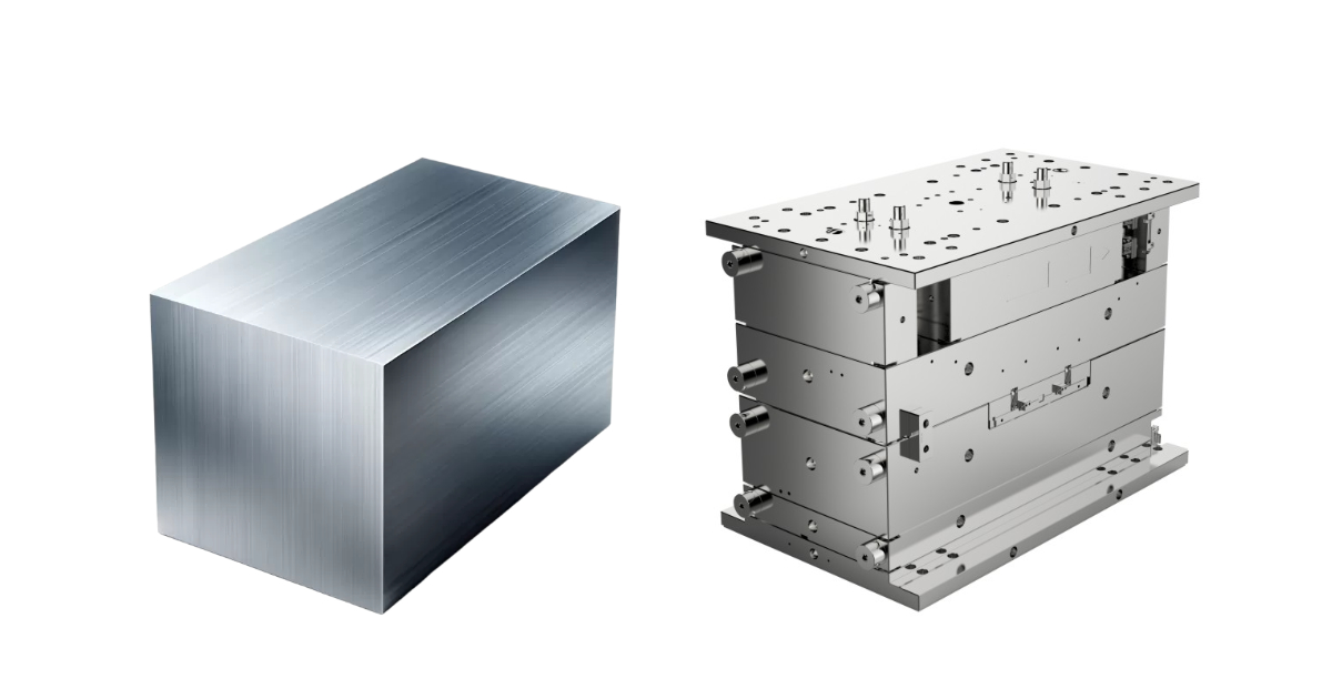
How Mold Manufacturing Works — From Steel Block to Production Tool
A customer once sent us a part file with a note: “We’ve been buying this part from a local molding shop for three years. They keep telling us the tool needs maintenance. Can you look at the mold?”
We opened it. The ejector pins were seized. The cooling channels hadn’t been cleaned since the mold was built. The gate had been enlarged with a hand file — a field modification that permanently altered the fill balance. The mold was four years old and had produced maybe 80,000 shots. A properly built production mold should reach 500,000 shots before its first major overhaul.
The mold wasn’t worn out. It had been built wrong from the start.
Understanding how a plastic injection mold is actually made — the sequence of operations, the equipment, the steel grades, the quality checks — helps you evaluate suppliers, ask the right questions during DFM review, and understand what you’re paying for. This guide walks through the entire mold manufacturing process, from a block of steel to a production-ready tool.
What Is an Injection Mold?
An injection mold is a precision tool that forms molten plastic into a specific shape under high pressure. It is not a single piece of metal. It is an assembly of precision-machined steel plates, inserts, and components that must close, fill, cool, open, and eject — repeatedly, at cycle times measured in seconds, for hundreds of thousands of cycles.
A standard two-plate cold-runner mold consists of:
| Component | Function |
|---|---|
| Cavity (A-side) | Fixed half — forms the exterior surface of the part. Mounted to the stationary platen. |
| Core (B-side) | Moving half — forms the interior surface and contains the ejector system. Mounted to the moving platen. |
| Sprue bushing | Entry point where the injection nozzle seats against the mold |
| Runner system | Channels that distribute melt from the sprue to each cavity gate |
| Gates | Narrow openings where melt enters each cavity |
| Cooling channels | Drilled or milled passages for water or oil circulation — remove heat from the steel |
| Ejector system | Pins, blades, sleeves, or stripper plates that push the solidified part off the core |
| Return pins | Spring-loaded pins that retract the ejector system when the mold closes |
| Guiding system | Leader pins and bushings that align the core and cavity halves during closure |
| Venting | Shallow channels (0.01–0.03mm deep) at the parting line to allow air escape |
Hot runner molds replace the cold runner with a heated manifold — eliminating the runner as waste, reducing cycle time, and improving gate quality. Multi-cavity molds replicate the same cavity geometry multiple times to produce several parts per cycle. Family molds combine different part geometries in one mold — common for assemblies. Each configuration changes the manufacturing approach.
Phase 1: Mold Design
Mold manufacturing begins on screen, not on the shop floor. The mold design phase produces a complete 3D model of the tool — every plate, insert, component, and channel — before a single piece of steel is cut.
The DFM Review
The design phase starts with a Design for Manufacturability (DFM) analysis of the customer’s part. The mold designer evaluates:
- Parting line location. Where the two mold halves separate. Determines which surfaces go to the cavity and which to the core. A poor parting line creates visible witness lines on cosmetic surfaces or makes the part impossible to eject.
- Gate position and type. Edge gate, submarine gate, pin gate, or valve gate. Gate location determines fill pattern, weld line position, and gate vestige location.
- Draft angle adequacy. Every surface parallel to mold opening needs taper. The designer checks draft against surface texture requirements — deeper texture needs more draft.
- Undercut identification. Features that prevent straight-pull ejection need side actions (slides), lifters, or collapsible cores. Each undercut mechanism adds tooling cost and maintenance complexity.
- Cooling layout feasibility. The designer checks whether even cooling is achievable for the part geometry — deep ribs, tall bosses, and thick sections create hot spots that extend cycle time.
- Ejector placement. The designer maps ejector pin locations to non-cosmetic surfaces and verifies sufficient ejection area for the expected ejection force.
A DFM report is returned to the customer with specific recommendations. No steel is cut until the customer approves the mold design.
3D Mold Design
Once the DFM is approved, the mold designer builds the complete 3D mold assembly in CAD (typically NX, SolidWorks, or Creo). The output is not just a model — it is the manufacturing instruction set:
- Individual steel plate drawings with machining datums and tolerances
- Electrode models for EDM (the negative shape that will be burned into the steel)
- Cooling channel routing with inlet/outlet locations
- Ejector system layout with pin diameters, lengths, and positions
- Assembly drawings showing component relationships and fastener locations
A single-cavity production mold for a part the size of a smartphone housing typically contains 80–150 individual components. Every one of them is modeled, dimensioned, and toleranced before machining begins.
Phase 2: Steel Selection
The steel grade determines the mold’s hardness, wear resistance, corrosion resistance, polishability, and thermal conductivity — and its cost. The selection is driven by the production volume, material, and surface finish requirements.
| Steel Grade | Hardness (HRC) | Typical Use |
|---|---|---|
| P20 | 28–32 (pre-hardened) | General-purpose production tooling. Good machinability. Standard choice for most programs. |
| H13 | 48–52 (hardened) | High-volume production (>500K shots). Excellent wear resistance at elevated temperatures. Standard for automotive programs. |
| S136 / 420SS | 48–52 (hardened) | Stainless. High polishability (SPI A1 mirror). Corrosion-resistant. Required for PVC, flame-retardant grades, and medical/optical applications. |
| NAK80 | 38–42 (pre-hardened) | Excellent polishability without hardening. Used for high-gloss cosmetic surfaces — consumer electronics, appliance fascias. |
| 718H | 33–38 (pre-hardened) | Improved P20 variant with better polishability. General-purpose with cosmetic capability. |
| Aluminum (7075-T6) | — | Prototype and bridge tooling only. Rapid machining. Typical life: 5,000–20,000 shots. |
Material-specific considerations:
- Glass-filled resins (PA66-GF30, PBT-GF30) require hardened steel (H13 minimum). Glass fibers are abrasive — they wear aluminum tooling within a few thousand shots.
- PVC and flame-retardant grades release corrosive gases during molding. Stainless steel (S136) or chrome-plated cavities are required.
- Optical and high-gloss cosmetic parts demand S136 or NAK80 with full polish. Any steel with porosity or inclusions will show on the part surface.
At JBRplas, steel stock is inspected on receipt for hardness and composition. Every block is stamped with its heat number and recorded against the mold project — traceable from steel mill to finished mold.
Phase 3: CNC Rough Machining
With the design approved and steel selected, machining begins. The first step is roughing — removing the bulk of material to create the approximate cavity and core geometry.
CNC roughing uses carbide end mills running at high feed rates. The objective is material removal speed, not surface finish. Roughing leaves 0.3–0.5mm of stock on all surfaces for subsequent finishing operations.
On a mold the size of a shoebox, roughing might run for 2–6 hours per plate. For larger automotive molds, roughing can run continuously for 20–40 hours.
Key parameters during roughing:
- Step-over: 50–70% of tool diameter for bulk material removal
- Depth of cut: 0.5–2.0mm per pass, depending on tool diameter and steel hardness
- Coolant: Flood coolant for P20 and NAK80; air blast or MQL for hardened steels (thermal shock risk)
After roughing, the cavity and core are recognisable but rough — tool marks are visible, dimensional tolerance is ±0.1mm, and surface finish is coarse.
Phase 4: EDM — Electrical Discharge Machining
CNC milling can only cut what the tool can reach. Sharp internal corners, deep narrow slots, and features inaccessible to an end mill require EDM — a process that removes metal by controlled electrical discharge (spark erosion) rather than mechanical cutting.
Sinker EDM (Ram EDM)
A graphite or copper electrode — machined to the negative shape of the feature — is lowered into the steel workpiece. A pulsed DC current jumps the gap between electrode and steel, vaporizing metal one microscopic particle at a time. The dielectric fluid (typically mineral oil) cools the spark zone and flushes away eroded particles.
Sinker EDM is used for:
- Deep ribs narrower than an end mill can reach
- Sharp internal corners (CNC leaves a radius equal to tool radius)
- Text and logos on the cavity surface
- Complex geometries impossible to machine with a rotating tool
A single mold may require 5–15 custom electrodes, each machined to a specific geometry and used for a specific feature. Electrode wear is accounted for — critical dimensions use roughing and finishing electrodes, with the finishing electrode removing only 0.02–0.05mm.
Wire-cut EDM
A continuously-fed brass or zinc-coated wire (0.1–0.3mm diameter) cuts through hardened steel with ±0.003mm accuracy. Used for:
- Precision shut-off surfaces where core and cavity meet
- Ejector pin holes and guide pin bores
- Slender apertures and slots
Wire EDM can cut steel that is already hardened to 50+ HRC — something no end mill can do economically — making it the standard method for ejector pin holes and precision features in hardened tool steel.
Phase 5: CNC Finishing and Hard Milling
After EDM, the cavity and core return to CNC for finishing — the final pass that brings surfaces to dimensional tolerance and plateau finish.
Finishing uses smaller-diameter ball end mills (R0.5 to R3) with step-over of 0.05–0.15mm between passes. The objective shifts from material removal to surface quality. A typical finishing pass on a smartphone-sized cavity runs 4–12 hours.
Hard milling — finish machining on steel that is already hardened to 48–52 HRC — is performed with micro-grain carbide tools at high spindle speeds (15,000–40,000 RPM) with very low depth of cut (0.02–0.05mm). Hard milling can achieve ±0.005mm tolerance directly on hardened steel, reducing the amount of EDM work required and eliminating the need for post-hardening machining on some features.
At this stage, the cavity and core surfaces are at dimensional tolerance. Surface finish is typically SPI B-2 (fine milled finish) — suitable for many industrial parts as-is, and ready for polishing for cosmetic applications.
Phase 6: Grinding
Surface grinding produces flat, parallel, and square surfaces on mold plates — the precision reference planes that determine how the mold assembles and closes.
Every plate in the mold stack — clamp plate, cavity plate, core plate, support plate, spacer blocks, ejector plates — goes through surface grinding on both faces. The requirements are:
- Flatness: 0.01mm across 300mm
- Parallelism: 0.01mm between faces
- Squareness: 0.01mm between adjacent edges
Plates that are out of parallel cause the mold to close unevenly — creating flash on one side, excessive clamp force on the other. Grinding is the operation that makes the difference between a mold that runs flash-free and one that fights the press.
Precision grinding is also used for:
- Ejector pin faces (flush or slightly recessed)
- Slide faces and guide surfaces
- Gate insert faces
- Shut-off surfaces (core-to-cavity mating surfaces)
Phase 7: Polishing
For parts requiring cosmetic surfaces — consumer electronics, appliance fascias, automotive interior trim — the mold cavity and core must be polished to a mirror or near-mirror finish. Polishing is a manual process: a skilled polisher using diamond paste, polishing stones, and rotary tools, working progressively through grit sizes.
SPI (Society of the Plastics Industry) finish standards:
| SPI Grade | Finish | Method | Typical Application |
|---|---|---|---|
| A-1 | #1 Diamond — 0–1μm Ra | Grade #3 diamond compound | Optical lenses, transparent parts |
| A-2 | #2 Diamond — 0.025μm Ra | Grade #6 diamond compound | High-gloss cosmetic housings |
| A-3 | #3 Diamond — 0.05μm Ra | Grade #15 diamond compound | Gloss consumer electronics |
| B-1 | 600 Grit Paper | Fine grit stone | Semi-gloss enclosures |
| B-2 | 400 Grit Paper | Medium grit stone | Matte industrial finish |
| B-3 | 320 Grit Paper | Coarse grit stone | Non-cosmetic parts |
| C-1 | 600 Stone | — | General industrial |
| C-2 | 400 Stone | — | Hidden surfaces only |
A full SPI A-2 polish on a smartphone-sized cavity takes 8–16 hours of skilled manual work. Every polishing step removes material — the polisher must maintain dimensional tolerance while improving surface finish, which requires constant measurement and judgement.
For textured surfaces (VDI or Mold-Tech), polishing is followed by chemical etching — a photoresist-and-acid process that creates a controlled texture pattern. The texture depth determines the required draft angle (deeper texture needs more draft to release).
Phase 8: Assembly and Fitting
With all plates machined, ground, and polished, the mold is assembled. This is not a bolt-together operation. It is a fitting process — every moving component is checked for clearance, alignment, and function.
Assembly sequence:
- Cooling circuit pressure test. Cooling channels are pressurized with water or air to verify no leaks at fittings or cross-drilled intersections.
- Core and cavity mounting. The machined inserts are mounted into their pockets in the cavity and core plates. Dowel pins and cap screws provide location.
- Ejector system assembly. Ejector pins, return pins, and springs are fitted. Each pin must slide freely in its bore — binding indicates misalignment that must be corrected.
- Slide and lifter installation. Side actions and lifters are installed and cycled manually. Timing and travel are verified.
- Guiding system alignment. Leader pins and bushings are checked — the mold must close smoothly with no binding or interference.
- Venting verification. Vent channels at the parting line and around ejector pins are inspected.
- Full closure check. The mold is closed under light pressure. The fitter checks for even contact at the parting line using Prussian blue — uneven contact indicates a parallelism or flatness issue.
The assembled mold is then mounted on the designated injection press for the first trial.
Phase 9: Mold Trial — T1
The T1 (first trial) is where months of design and machining meet hot plastic for the first time. It is a verification step — not a production run.
What happens at T1:
- Parameter development. The process engineer establishes initial injection pressure, hold pressure, melt temperature, mold temperature, cooling time, and cycle time. This is the starting process window — it will be refined through T2 and into production.
- Fill analysis. Short shots (intentionally incomplete fills) are molded to verify gate location and fill pattern. The engineer checks that melt fronts meet at the expected weld line locations.
- Dimensional check. T1 parts are measured on CMM against the drawing. All dimensions are recorded. Dimensions that are out of tolerance are identified for mold adjustment.
- Visual inspection. Surface finish, gate vestige, ejector pin marks, weld line visibility, flash, and sink marks are documented.
- Function test. Snap-fits are tested, threaded features are checked with go/no-go gauges, assembly fit is verified with mating components.
The T1 report documents everything: machine parameters, cycle time, part weight, dimensions, photographs of parts and defect areas, and an action list for mold adjustments.
Customers should expect T1 parts that are close to target but not final. The mold has not been adjusted yet. Dimensional corrections, gate refinements, and surface finish adjustments happen between T1 and T2.
Phase 10: Mold Adjustments and T2
Based on the T1 report, the mold returns to the toolroom for adjustments:
- Dimensional corrections. If a feature is too large, steel is removed from the cavity. If too small, the core is reduced. Corrections are typically 0.02–0.10mm.
- Gate refinement. If fill imbalance or gate vestige is unacceptable, the gate geometry is modified.
- Venting adjustments. If burn marks or short shots occurred, venting is deepened or additional vents are added.
- Ejector system tuning. If ejection marks are deep or parts are sticking, ejector forces are balanced.
- Polish refinement. If surface finish is below specification, additional polishing is performed.
A T2 trial follows — running the adjusted mold with the same material and parameters. T2 confirms that all corrections are effective and the part is within specification. For straightforward parts with accurate mold design, T2 is typically the final trial before production release. Complex parts may require a T3.
How Long Does Mold Manufacturing Take?
| Mold Type | Design | Machining + EDM | Polishing | Assembly + Trial | Total (Typical) |
|---|---|---|---|---|---|
| Simple single-cavity (P20) | 3–5 days | 8–12 days | 1–3 days | 3–5 days | 15–25 days |
| Medium complexity (P20) | 5–8 days | 12–18 days | 3–5 days | 5–7 days | 25–38 days |
| High complexity (H13) | 8–12 days | 18–25 days | 5–10 days | 7–10 days | 38–57 days |
| Multi-cavity (hot runner) | 12–18 days | 25–35 days | 8–12 days | 10–14 days | 55–79 days |
These are working days from design approval. Actual lead time depends on the specific geometry, cavity count, steel grade, and current shop loading. A committed T1 date is provided at the time of order — not an estimate, a commitment.
What Separates a Good Mold from an Average One
A mold that produces 1,000 acceptable parts is easy. A mold that produces 500,000 parts — consistently, with minimal maintenance, at the quoted cycle time — is the result of decisions made at every phase of manufacturing:
- Cooling design. A poorly cooled mold adds 3–8 seconds to every cycle. At 500,000 cycles, that is 400–1,100 hours of extra press time. The cost of additional cooling channels is recovered within the first 50,000 shots.
- Venting. Adequate venting prevents burn marks and short shots. Insufficient venting creates problems that no amount of process adjustment can fix — the mold must be pulled and reworked.
- Ejector balance. Uneven ejection distorts parts on every cycle. A properly balanced ejector system distributes force across enough area that ejection leaves no permanent mark.
- Steel quality. Steel that has not been properly stress-relieved before machining will move during EDM and heat treatment. A mold that is not dimensionally stable is a mold that produces parts that drift out of tolerance.
- Fit and alignment. Loose fitting between core and cavity produces flash — plastic that leaks into the parting line gap. Tight fitting with poor alignment produces galling — metal-on-metal friction that damages both halves. The difference is hundredths of a millimeter and years of experience.
Frequently Asked Questions
Can I supply my own mold design? Yes. We accept customer-supplied designs and perform a manufacturing review before machining. If the review identifies issues — insufficient draft, impossible undercut geometry, cooling channel conflicts — we return a marked-up design for your approval before cutting steel.
What is the difference between a prototype mold and a production mold? A prototype mold (aluminum or soft P20) is built for speed and cost — typical life 5,000–20,000 shots. A production mold (hardened H13 or S136) is built for longevity — rated life 500,000 to 1,000,000+ shots. Prototype molds use simpler cooling, fewer ejectors, and may not include features like automatic degating or hot runner. The parts are dimensionally identical. The mold is not.
Do you warranty the mold? Standard warranty: 1,000,000 shots or 1 year (whichever comes first) on P20 and H13 production tooling. The warranty covers material defects and workmanship. It does not cover damage from improper operation, contaminated material, or failure to perform routine maintenance. The specific shot life warranty is documented in the mold supply agreement.
Can you reverse-engineer a mold from an existing part? Yes. Provide a reference part and 2D drawing with tolerances. We scan the part dimensionally to establish a baseline, then design and build a mold to produce parts that match the reference within the drawing tolerance.
What documentation do you provide with a new mold? Every mold ships with: mold assembly drawing (2D), 3D mold model (STEP format), cooling circuit diagram with inlet/outlet identification, ejector layout drawing, spare parts list (ejector pins, springs, O-rings), recommended maintenance schedule, and initial process setup sheet from T1 trial.
A mold is not a commodity. It is a precision-manufactured asset that determines the quality, cost, and reliability of every part it produces for the next decade. The process described here — design through T2 — is the standard at JBRplas. Every mold we ship has been through every one of these phases, documented at each step.
Submit your part file for a free DFM review and mold quote →