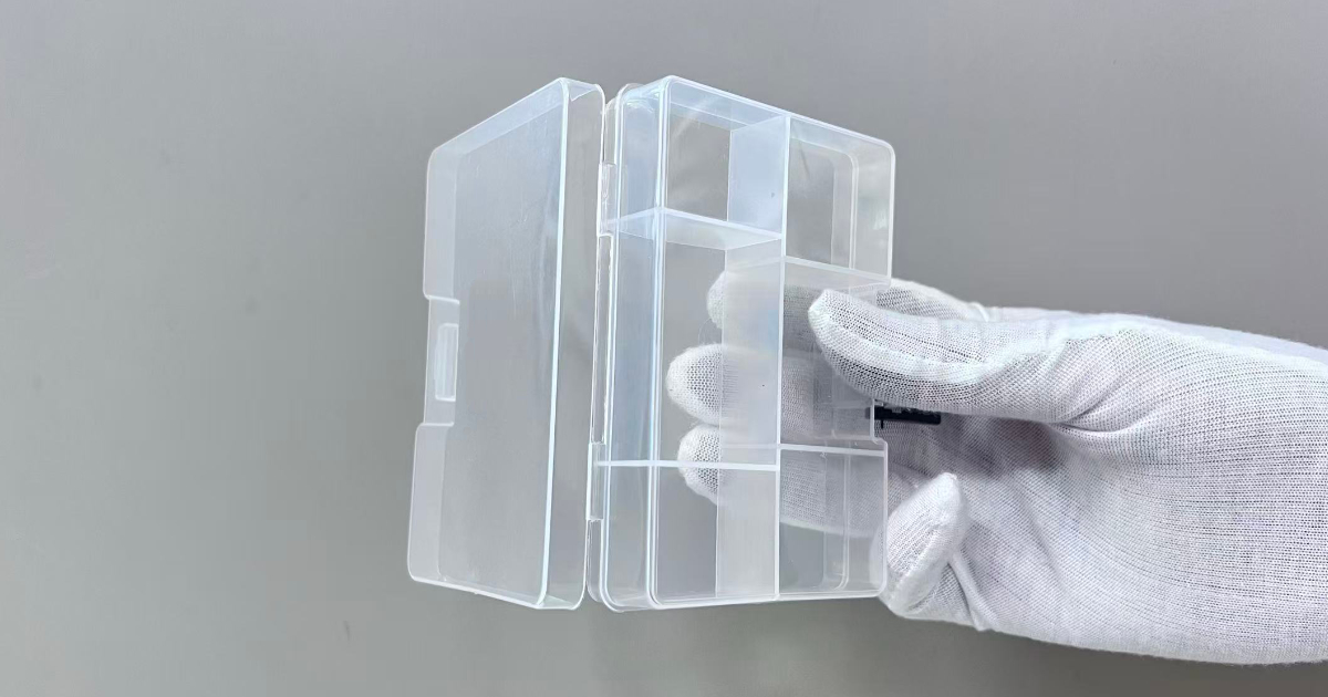
Living Hinge Design Guide — Geometry, Material Selection, and Fatigue Life for Injection Molded Hinges
A product designer at a consumer goods company is developing a snap-close container for a personal care product. The lid and base are a single injection-molded part connected by a living hinge — a thin, flexible strip of plastic that bends repeatedly without breaking. The first prototype hinge worked for approximately 50 cycles before it cracked at the centerline and separated. The second prototype, with a thinner hinge, worked for 200 cycles before the same failure. The third, with a thicker hinge, failed at 30 cycles — the hinge was too stiff, and the bending stress concentrated at the hinge root rather than distributing across the hinge length.
The designer asked the tooling engineer for a material change. The tooling engineer asked the designer what the hinge thickness was. The answer: 0.8 mm, measured from the CAD model. The correct answer for a PP living hinge designed for 50,000+ cycles: 0.25–0.35 mm.
Living hinges are the only injection-molded feature where the structural requirement — stiffness to hold the lid closed — and the functional requirement — flexibility to bend without breaking — must coexist in the same 0.3 mm of plastic. Like snap-fits, living hinges rely on controlled plastic deformation: snap-fits deform during assembly and spring back; living hinges deform during every use cycle and must not break. The design rules for living hinges are narrow, material-specific, and unforgiving of process shortcuts. This guide covers the geometry, material selection, gate placement, and processing conditions that determine whether a living hinge survives one cycle, one thousand cycles, or one million cycles.
The Physics of a Living Hinge
A living hinge works by plastic deformation of the polymer at the hinge centerline, combined with elastic bending in the hinge arms. When the lid is closed, the hinge bends through approximately 150–180° around a radius at the centerline. The outer surface of the hinge (farthest from the centerline) stretches in tension; the inner surface compresses. The material at the hinge centerline undergoes the highest strain — the polymer chains in this region must elongate, orient, and realign without fracturing.
The key to living hinge durability is molecular orientation. When the polymer melt flows through the thin hinge section during filling, the polymer chains align in the direction of flow. In polypropylene — the dominant material for living hinges — this flow-induced orientation transforms the normally brittle (at thin sections) polymer into a highly ductile, fiber-like structure at the hinge. The oriented PP can withstand strains of 300–500% before failure, compared to 50–100% for unoriented PP.
The orientation must be in the direction of bending — the polymer chains must run perpendicular to the hinge centerline, aligned with the direction the hinge opens and closes. Flow across the hinge (parallel to the centerline) produces a hinge with no orientation in the bending direction — and a fatigue life measured in single digits.
This means that gate placement is the single most critical design decision for a living hinge. The gate must be positioned so that the melt flows through the hinge in the bending direction, not across it. For a rectangular container with the hinge along one edge, the gate should be on the opposite side of the part from the hinge, so the melt flows across the part, through the hinge, and into the lid — aligning the polymer chains perpendicular to the hinge centerline.
Hinge Geometry — The Four Parameters
A living hinge is defined by four geometric parameters:
| Parameter | Symbol | Typical Range | Function |
|---|---|---|---|
| Hinge thickness | t | 0.20–0.50 mm | Controls bending stiffness and strain at the centerline |
| Hinge radius | R | 0.25–0.75 mm | Distributes bending strain; larger radius = lower peak strain |
| Land length | L | 0.50–1.50 mm | Provides a flat section for molecular orientation; the “working length” of the hinge |
| Relief depth | D | 0.50–1.00 mm | Thins the part wall at the hinge to direct bending into the hinge rather than the adjacent wall |
The hinge cross-section resembles a thin flat bridge connecting two thicker walls. The relief on both sides of the hinge (top and bottom of the part wall) ensures that bending occurs in the thin hinge section rather than in the adjacent 2.0–3.0 mm walls — which would crack at the bending radius rather than flexing. The part design guidelines for wall thickness transitions apply here: the relief should transition from the nominal wall to the hinge thickness with a radius, not a sharp step.
Hinge Thickness — The Dominant Parameter
Hinge thickness controls the bending strain at the centerline. For a given bend angle, the strain is proportional to the hinge thickness divided by the bend radius: ε ≈ t / (2R). A thinner hinge reduces the strain and increases the fatigue life — but also reduces the bending stiffness, which determines how firmly the lid stays closed.
| Hinge Thickness (mm) | Approximate Fatigue Life (cycles) — PP | Bending Stiffness (Relative) | Typical Application |
|---|---|---|---|
| 0.15–0.20 | 500,000–2,000,000+ | Very low | High-cycle industrial hinges, packaging closures |
| 0.20–0.30 | 100,000–500,000 | Low | Consumer product containers, pill bottle caps |
| 0.30–0.40 | 10,000–100,000 | Medium | Toolbox latches, appliance doors |
| 0.40–0.50 | 1,000–10,000 | High | Structural hinges, heavy lids |
| >0.50 | <1,000 | Very high | Not recommended for living hinges — use a mechanical hinge |
The data assumes properly oriented PP, processed at the correct melt temperature, and gated for flow through the hinge. The same geometry in an unoriented PP, or gated for flow across the hinge, will fail at 1–5% of these cycle counts.
Hinge Radius
The radius at the hinge centerline distributes the bending strain over a curved rather than a sharp corner. A sharp corner (R <0.1 mm) concentrates the entire bending strain at a single line — the hinge cracks at that line within the first few flex cycles. A larger radius (R = 0.5–0.75 mm) spreads the strain over a broader zone, reducing the peak strain and increasing the fatigue life.
The radius should be at least 1.0–1.5× the hinge thickness. A 0.3 mm hinge with a 0.5 mm radius distributes the strain over a 0.5 mm curved zone. The same hinge with a 0.15 mm radius concentrates the strain at a near-sharp corner.
Land Length
The land length is the flat section of the hinge between the two radii — the straight portion where the polymer chains are oriented in the flow direction. A longer land length provides more oriented material to distribute the bending strain. A 1.0 mm land length on a 0.3 mm hinge provides approximately 3× the oriented material volume of a 0.3 mm land length.
The land length should be at least 2–3× the hinge thickness. Below 2×, the hinge is essentially a V-notch — a sharp corner that concentrates strain and fails rapidly.
Material Selection — PP Dominates, But Alternatives Exist
Polypropylene (PP) — The Reference Material
PP is the material of choice for living hinges because of its unique combination of properties: high elongation at yield (8–12%), excellent fatigue resistance, the ability to develop high molecular orientation during flow, and a cost of $2.00–3.00/kg. PP homopolymer provides the best hinge performance; PP copolymer (with ethylene content for impact modification) reduces hinge fatigue life by approximately 30–50% because the ethylene domains disrupt the molecular orientation.
| PP Grade | MFR (g/10 min) | Hinge Fatigue Life (Relative) | Notes |
|---|---|---|---|
| PP homopolymer, 2–4 MFR | 2–4 | 100% (reference) | Best hinge performance; requires higher fill pressure |
| PP homopolymer, 10–20 MFR | 10–20 | 80–90% | Good hinge performance; standard injection molding grade |
| PP homopolymer, 35–50 MFR | 35–50 | 50–70% | Lower orientation → lower fatigue life; easier to fill |
| PP copolymer (impact) | 10–20 | 30–50% | Ethylene disrupts orientation; use only if impact is primary |
| PP copolymer (random) | 10–20 | 40–60% | Better than impact copolymer, worse than homopolymer |
The material selection for a living hinge prioritizes the ability to develop and retain molecular orientation over all other properties. A low-MFR homopolymer PP — processed at the upper end of its melt temperature range to maximize flow-induced orientation — is the standard starting point.
Alternative Materials
| Material | Relative Hinge Performance | Limitations |
|---|---|---|
| PE (HDPE) | 50–70% of PP | Lower modulus = lower snap-close force; good chemical resistance |
| POM (Acetal) | 30–50% of PP | Higher stiffness; fatigue cracks propagate faster |
| PA6/66 (dry) | 20–40% of PP | Absorbs moisture → dimensional change at hinge; brittle when dry |
| TPE/TPO | Excellent flexibility, low cycle life | Low stiffness → poor snap closure; not a structural hinge |
| PC, ABS, PS | Not recommended | Brittle at thin sections; will not form a living hinge |
PE is the only practical alternative to PP for living hinges, and only for applications where the number of flex cycles is low (<1,000) or where PP’s chemical resistance or stiffness is insufficient. For any application requiring more than 1,000 cycles, PP homopolymer is the default answer.
Processing Conditions — The Invisible Design Parameter
A perfectly designed hinge geometry, gated correctly for flow through the hinge, will still fail within 100 cycles if the processing conditions do not develop molecular orientation in the hinge.
Melt Temperature — Hotter Is Better (to a Point)
PP processed at 230–250°C (the standard processing window) produces acceptable short-term mechanical properties but limited molecular orientation. PP processed at 260–280°C — the upper end of the PP processing window — produces a lower-viscosity melt that orients more readily during flow through the thin hinge section. The higher melt temperature also delays cooling in the hinge, giving the oriented polymer chains more time to relax into a stress-relieved configuration before freezing.
The trade-off: processing at 280°C increases the risk of thermal degradation if the residence time in the barrel exceeds 5–8 minutes. The mold cycle must be fast enough (typically <15 seconds for small PP parts) that the material does not sit at degradation temperature in the barrel.
Mold Temperature — Warmer Is Better
A mold temperature of 40–60°C — warmer than the standard 20–35°C for PP — slows the cooling of the hinge section. Slower cooling allows the oriented polymer chains to partially relax, reducing the residual stress in the hinge while preserving the orientation. A mold temperature that is too cold (<30°C) freezes the orientation stress into the part before relaxation can occur, producing a hinge that is highly oriented but also highly stressed — it will fail by stress cracking at the hinge centerline after a few hundred cycles.
Injection Speed — Fast Through the Hinge
The injection speed should be high (150–300 mm/s for a small part) to minimize the cooling of the melt as it flows through the thin hinge section. A slow injection speed allows the melt to cool in the hinge before the cavity is full, reducing the degree of orientation and producing a hinge with low fatigue life. A fast fill through the hinge is the processing equivalent of orienting the polymer chains — it is the same physics as thin-wall molding, applied specifically to the hinge cross-section.
Design Checklist
| # | Check | Pass/Fail Criterion |
|---|---|---|
| 1 | Gate placement | Gate must produce flow through the hinge in the bending direction |
| 2 | Hinge thickness | 0.20–0.40 mm for PP (<0.35 mm for >10,000 cycles) |
| 3 | Hinge radius | ≥1.0× hinge thickness (R ≥0.3 mm for a 0.3 mm hinge) |
| 4 | Land length | ≥2.0× hinge thickness (L ≥0.6 mm for a 0.3 mm hinge) |
| 5 | Material | PP homopolymer with MFR ≤20 g/10 min |
| 6 | Melt temperature | 260–280°C for PP (upper end of processing window) |
| 7 | Mold temperature | 40–60°C (warmer than standard PP settings) |
| 8 | Injection speed | High — fill the hinge section before the melt cools |
| 9 | Post-molding conditioning | Flex the hinge 2–3 times immediately after molding to cold-draw the centerline |
| 10 | Packing | Avoid over-packing the hinge — packing pressure can crush the thin section |
Post-Molding Conditioning
The first flex of a living hinge is the most important. Immediately after molding — while the part is still warm from the mold (40–60°C) — the hinge should be flexed through its full range of motion 2–3 times. This cold-drawing (actually warm-drawing at 40–60°C) plastically deforms the hinge centerline, creating a necked-down zone with extremely high molecular orientation. The polymer chains at the centerline are drawn from their as-molded semi-oriented state into a fully oriented, fiber-like structure that can withstand millions of flex cycles.
A hinge that is never flexed until the end user opens the container for the first time — weeks or months after molding, when the part is at room temperature (20–25°C) — has a significantly shorter fatigue life than a hinge that was conditioned at the molding machine. This is not a molding defect — it is a predictable consequence of unrelaxed orientation stress — and post-molding conditioning is the standard remedy for high-cycle living hinges.
Common Failure Modes
| Failure Mode | Appearance | Root Cause | Solution |
|---|---|---|---|
| Centerline crack | Crack at hinge midpoint, perpendicular to bend direction | Hinge too thick; strain exceeds material limit | Reduce hinge thickness to ≤0.35 mm |
| Edge-initiated crack | Crack starting at hinge edge and propagating inward | Sharp corner at hinge edge; stress concentration | Radius the hinge edges (R ≥0.2 mm) |
| Stress whitening before failure | White discoloration at hinge centerline after flexing | Over-orientation without relaxation; mold too cold | Increase mold temperature to 40–60°C |
| Brittle fracture (snap) | Hinge breaks on first or second flex | Flow across hinge rather than through it; no orientation | Relocate gate for flow through hinge in bend direction |
| Gradual stiffening | Hinge becomes stiffer with each cycle | PP molecular relaxation over time; creep in the hinge | Use homopolymer PP; pre-condition hinge at molding |
| Lid won’t stay closed | Hinge too thin; insufficient bending stiffness | Hinge thickness below 0.15 mm | Increase hinge thickness to 0.25–0.30 mm |
The product designer who started with a 50-cycle hinge crack ultimately specified a 0.30 mm hinge thickness with a 0.50 mm hinge radius, a 0.80 mm land length, and PP homopolymer at 12 MFR. The gate was relocated to the side opposite the hinge to produce flow through the hinge in the bending direction. Melt temperature: 270°C. Mold temperature: 50°C. The hinge was post-conditioned at the press with 3 flex cycles. The production parts survived 80,000 flex cycles in the customer’s validation test — exceeding the 50,000-cycle requirement and validating the container for a 5-year product warranty.
A living hinge is the only injection-molded feature where the polymer’s molecular structure — the orientation of the chains at the hinge centerline — is the design parameter that determines whether the part functions. The geometry, the material, and the process must all be aligned to produce that orientation — and the alignment is engineered, not discovered.