Insert Molding Design Guide — Metal Inserts, Thermal Expansion, and Pull-Out Strength
A design engineer at an industrial equipment manufacturer is finalizing a pump housing that bolts to a cast aluminum manifold. The housing is injection molded from glass-filled nylon — 2.8 mm walls, 180 × 120 mm footprint, 420 g part weight. Four M6 bolts pass through the housing into threaded holes in the manifold. The bolt torque specification is 12 N·m. The first prototype used self-tapping screws directly into molded nylon bosses. The screws stripped the plastic threads at 7 N·m during assembly — 40% below the torque specification.
The solution is insert molding: placing threaded metal inserts into the mold before injection so the plastic encapsulates them during the molding cycle. The insert provides the thread strength; the plastic provides the structural geometry. The same housing with brass M6 inserts molded in place achieved 18 N·m thread strength — a 50% margin above the assembly torque requirement.
Insert molding solves the thread-strength problem that limits the use of plastic for mechanically fastened assemblies. But it introduces a different set of challenges: the metal insert and the plastic shrink at different rates, creating residual stress at the interface. An insert that is too small or too smooth pulls out under load. An insert that is positioned without accounting for mold shut-off surfaces creates flash that blocks the threaded hole. This guide covers insert types, boss design, and the mechanical and thermal considerations that determine whether an inserted joint holds or fails.
Insert Molding vs Overmolding — What Is the Difference
Insert molding and overmolding are often conflated, but they are distinct processes:
| Feature | Insert Molding | Overmolding |
|---|---|---|
| What is placed in the mold | A pre-made component (metal, ceramic, another plastic) | Nothing — the first shot is molded, then the second material is molded over it |
| Bond mechanism | Mechanical interlock (plastic shrinks onto the insert) | Chemical or mechanical bond between two plastic materials |
| Typical application | Threaded fasteners, electrical contacts, reinforcing pins | Soft-touch grips, seals, two-color cosmetic parts |
| Mold complexity | Adds insert loading step; manual or automated | Requires two-shot machine or two molds with part transfer |
| Process cycle | Single-shot; insert loading adds to cycle time | Two-shot: rotary or shuttle; two-cycle: requires part transfer |
Insert molding is fundamentally a single-shot process that incorporates a pre-existing component. Overmolding is fundamentally a two-material process. The design rules are different because the failure modes are different — insert molding fails by insert pull-out or plastic cracking around the insert; overmolding fails by bond-line delamination between the two materials. The injection molding tolerances around insert features are tighter than general part tolerances because the insert position determines the mating fastener alignment.
Insert Types and Selection
Inserts are categorized by how they anchor into the plastic:
Threaded Inserts
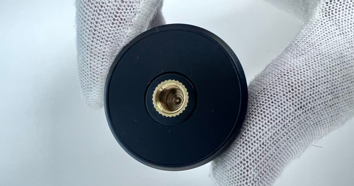
The most common insert type. A metal cylinder with internal threads and external anchoring features. Available in brass (most common), stainless steel (corrosion resistance), and aluminum (weight reduction).
| Type | Anchoring Mechanism | Best For | Limitations |
|---|---|---|---|
| Knurled | Diamond or straight knurl on OD | General-purpose; high torque | Knurl can crack thin boss walls |
| Hexagonal | Hex OD resists rotation | High torque-out resistance | Requires thicker boss wall |
| Undercut / Grooved | Radial grooves or undercuts | High pull-out resistance | Lower torque-out than knurled |
| Flanged | Flange at one end for bearing surface | Compression loads; prevents push-through | Requires countersink in boss |
Insert dimensions scale with thread size. For a standard M6 brass insert:
| Feature | Typical Value |
|---|---|
| Insert OD | 8.0–9.0 mm |
| Insert length | 10–15 mm |
| Knurl depth | 0.2–0.4 mm |
| Pilot diameter (lead-in) | 0.3–0.5 mm smaller than body |
| Wall thickness around insert | ≥1.5× insert OD or 0.5× nominal wall, whichever is greater |
Non-Threaded Inserts
Not every insert needs threads. Pins, bushings, and reinforcement elements are molded in for mechanical functions other than fastening:
- Locating pins — Hardened steel pins that provide wear-resistant bearing surfaces or alignment datums for assembly. The pin is ground to a precise diameter; the plastic encapsulates the retention features.
- Electrical contacts — Brass or phosphor bronze terminals molded into connectors and switch housings. The contact must remain flash-free on the functional surface — requiring a positive shut-off in the mold at each contact.
- Reinforcement pins — Steel or composite rods that carry bending loads across a plastic part. Used in structural applications where the plastic alone would deflect excessively.
- Bushings and bearings — Sintered bronze or PTFE-lined bushings for rotating shafts. The bushing provides the bearing surface; the plastic provides the housing geometry.
The Thermal Expansion Problem
Metal and plastic shrink at different rates when cooling from the molding temperature to room temperature. This differential shrinkage is the defining engineering challenge of insert molding.
| Material | CTE (Coefficient of Thermal Expansion) | Shrinkage from 250°C to 25°C |
|---|---|---|
| Brass | 19 × 10⁻⁶ /°C | 0.43% |
| Steel | 12 × 10⁻⁶ /°C | 0.27% |
| Aluminum | 23 × 10⁻⁶ /°C | 0.52% |
| Nylon 6/6 (unfilled) | 80–100 × 10⁻⁶ /°C | 1.8–2.3% |
| Nylon 6/6 (30% GF) | 30–40 × 10⁻⁶ /°C | 0.7–0.9% |
| ABS | 70–90 × 10⁻⁶ /°C | 1.6–2.0% |
| PC | 65–70 × 10⁻⁶ /°C | 1.5–1.6% |
| PBT (30% GF) | 30–40 × 10⁻⁶ /°C | 0.7–0.9% |
| PP (unfilled) | 100–150 × 10⁻⁶ /°C | 2.3–3.4% |
| PEEK (unfilled) | 45–55 × 10⁻⁶ /°C | 1.0–1.2% |
The cycle works like this: the mold closes around a cold (room temperature) insert. Hot plastic at 200–350°C flows around the insert. The plastic cools and shrinks. The insert, now heated by the plastic, also shrinks as it cools — but at roughly one-quarter to one-sixth the rate of the plastic. The net effect: the plastic shrinks onto the insert, creating a compressive hoop stress that provides the mechanical grip.
This sounds like good news — the plastic grips the insert. And for most insert designs, it is. But two failure modes can occur:
Hoop stress cracking. If the plastic shrinks too aggressively onto a rigid insert — particularly with unfilled, high-shrinkage materials like unfilled nylon or PP — the tensile hoop stress in the plastic around the insert can exceed the material’s tensile strength. The result is radial cracking emanating from the insert location. Glass-filled materials reduce this risk because the glass fibers lower both the CTE and the absolute shrinkage, reducing the hoop stress at the insert interface. The boss wall thickness also matters: a boss wall too thin cannot absorb the shrinkage stress; a boss wall too thick creates a localized thick section that produces a sink mark on the opposite surface.
Loosening at elevated temperature. A threaded insert that is tight at room temperature may loosen at 80°C because the plastic expands more than the metal when heated, reducing the compressive grip at the interface. This is the thermal ratchet: tight when cold, loose when hot. The solution is an anchoring geometry (knurl, undercut, hexagonal OD) that provides mechanical interlock independent of thermal grip.
Boss Design for Molded-In Inserts
The boss — the cylindrical protrusion in the plastic that surrounds the insert — is the critical design feature. The boss geometry determines insert retention, mold filling around the insert, and the cosmetic quality of the opposite surface.
Boss Wall Thickness
| Insert OD | Recommended Boss Wall | Minimum Boss Wall |
|---|---|---|
| ≤6 mm | 2.0–3.0 mm | 1.5 mm |
| 6–10 mm | 2.5–4.0 mm | 2.0 mm |
| 10–16 mm | 3.5–6.0 mm | 2.5 mm |
| >16 mm | 0.4–0.6× insert OD | 0.3× insert OD |
The boss wall must be thick enough to carry the hoop stress from plastic shrinkage and the mechanical load from fastener torque. But it must also be thin enough to avoid creating a sink mark on the opposite surface — the boss creates a localized thick section at the base where it joins the nominal wall. The standard rib-to-wall ratio rule applies: the boss wall at the base should be 0.5–0.6× the nominal wall thickness to prevent sink.
Boss Height
The boss should extend 0.5–1.0 mm above the top of the insert to provide a lead-in for the mating fastener. The total boss height = insert length + 0.5–1.0 mm. For a 12 mm long insert, the boss is 12.5–13.0 mm tall.
Draft Angle
Bosses require draft on both the OD (for mold release) and the ID (if the bore is molded rather than the insert forming it):
- OD draft: 1–2°, measured from the vertical. The draft tapers the boss from thick at the base to thin at the top.
- ID draft: 0.5–1°, if the insert does not form the bore. Minimum draft for a core pin that will be withdrawn from the boss ID.
Undercut at the Insert Base
The most pull-out resistant insert designs incorporate a positive undercut — a groove, shoulder, or recess in the insert body that the plastic fills during molding. When the plastic shrinks, it locks into this undercut, creating a mechanical interlock that resists pull-out even if the thermal grip loosens at elevated temperature. The undercut depth should be 0.3–0.5 mm for inserts up to 10 mm OD and 0.5–0.8 mm for larger inserts.
Pull-Out and Torque-Out Strength
Two mechanical failure modes define insert retention design:
Pull-Out Strength (Axial Load)
The force required to pull the insert axially out of the plastic boss. Governed by:
- Hoop stress grip: The radial compressive force from plastic shrinkage, multiplied by the coefficient of friction between the insert and plastic. This is the primary retention mechanism for smooth inserts.
- Undercut shear: The plastic in the insert’s undercut feature must shear off for the insert to be pulled out. The shear area is the cylindrical surface area of the undercut depth multiplied by the insert circumference. The shear strength of the plastic at the undercut diameter determines the pull-out load.
- Boss tensile strength: The boss itself must not fracture. The tensile stress area is the annular cross-section of the boss wall.
For a typical M6 brass knurled insert in glass-filled nylon with a 9 mm OD, 12 mm length, and a 2.5 mm boss wall:
| Failure Mode | Approximate Load Capacity |
|---|---|
| Hoop stress friction grip | 800–1,200 N |
| Undercut shear | 2,500–3,500 N |
| Boss tensile failure | 4,000–5,500 N |
| Limiting factor | Hoop stress grip (~1,000 N) |
The hoop stress grip is typically the limiting factor. Adding an undercut shifts the limiting factor to the undercut shear, roughly tripling the pull-out strength. This is why knurled and undercut inserts are standard for mechanically loaded applications — the smooth-body insert relies entirely on thermal grip, which varies with temperature and material lot.
Torque-Out Strength (Rotational Load)
The torque required to rotate the insert in the boss during fastener tightening. Governed by:
- Knurl engagement: The knurl teeth bite into the plastic, providing mechanical resistance to rotation. Diamond knurls provide bidirectional resistance; straight knurls provide unidirectional resistance (better in one direction than the other).
- Hexagonal OD geometry: A hexagonal insert OD prevents rotation entirely — the plastic fills the hexagonal cavity, and the insert cannot rotate without shearing the plastic at all six corners simultaneously. This is the highest torque-out resistance geometry.
For the same M6 insert:
| Knurl Type | Approximate Torque-Out |
|---|---|
| Smooth (no knurl) | 1–3 N·m |
| Straight knurl | 5–10 N·m |
| Diamond knurl | 8–15 N·m |
| Hexagonal OD | 15–25 N·m |
The torque-out requirement is determined by the assembly torque of the mating fastener. A design margin of 2× over the assembly torque is recommended: if the bolt is torqued to 12 N·m, the insert torque-out strength should be at least 24 N·m.
Mold Design for Insert Molding
Insert molding adds a step to the molding cycle: insert loading. The mold opens, the previous part is ejected, and an operator or robot places inserts into the mold before the next cycle. This step directly adds to the cycle time and introduces a quality risk — a dislodged insert damages the mold.
Insert Retention in the Mold
The mold must hold the insert precisely during mold closing and injection. At injection pressures of 80–120 MPa, the melt flow can displace an insert that is not positively retained:
- Pin retention: A spring-loaded or retractable pin that engages the insert ID. The pin is withdrawn before or during ejection.
- Magnetic retention: For ferrous inserts, a magnet embedded in the mold steel holds the insert. Effective for small, lightweight inserts; insufficient for inserts over approximately 20 g or in high-pressure applications.
- Interference fit: The insert OD has a slight interference with a recess in the mold cavity. The insert is press-fit into the recess by the operator. Reliable but adds operator load time.
- Vacuum retention: A vacuum port in the mold holds the insert against the cavity wall. Used for flat, non-ferrous inserts (electrical contacts, brass terminals).
Flash Prevention at the Insert
The mold must seal against the insert surface to prevent plastic from flowing onto functional surfaces:
- Threaded inserts: A retractable core pin that threads into the insert ID seals the threads and prevents plastic ingress. The pin is unscrewed during ejection, or the part is ejected with the pin retracted and the insert threads are clean.
- Electrical contacts: A positive shut-off surface ground to a 0.02 mm clearance against the contact surface. The shut-off must be inspected every 5,000–10,000 shots for flash buildup at the shut-off edge.
- Through-hole inserts: Inserts with a through-hole (bushings, bearings) require a core pin that passes through the insert and seals at both ends. The pin transfers the insert retention force and provides the shut-off.
Common Insert Molding Defects
| Defect | Appearance | Root Cause | Solution |
|---|---|---|---|
| Insert pull-out (in service) | Insert pulls out of boss under load | Insufficient undercut, smooth insert body, material creep at elevated temperature | Specify knurled or undercut insert; verify CTE compatibility |
| Radial cracks around insert | Cracks radiating from insert in boss wall | Excessive hoop stress from plastic shrinkage; boss wall too thin | Increase boss wall; use lower-shrinkage material (glass-filled) |
| Flash in threaded hole | Plastic in insert threads | Core pin not sealing against insert face; pin clearance too large | Inspect core pin fit; reduce clearance to <0.03 mm |
| Insert displaced during molding | Insert not in design position; tilted or pushed into boss | Insert not retained in mold; injection pressure displaced it | Use positive retention (pin, magnet, interference) |
| Sink mark opposite boss | Visible depression on surface opposite insert boss | Boss wall too thick at base; localized thick section | Reduce boss wall to 0.5–0.6× nominal wall; add core-out at boss base |
| Insert loose after thermal cycling | Insert rotates or pulls out after temperature exposure | CTE mismatch; thermal grip lost at elevated temperature | Use mechanical interlock (undercut or knurl); verify material pairing |
| Cold slug at insert | Incomplete filling around insert; visible knit line at insert surface | Insert too cold; melt front chills on contact with insert | Preheat inserts to 80–120°C before loading; increase injection speed |
Preheating inserts is the single most effective process control for insert molding quality. An insert at room temperature (25°C) contacted by 280°C melt creates an instantaneous chill layer at the insert surface — the plastic skin freezes before it can flow into the insert’s knurl or undercut details. Preheating inserts to 80–120°C reduces the thermal shock by 60–70°C and allows the melt to flow fully into the retention features before freezing. Induction heating, hot-air preheating stations, or heated insert magazines integrated into the automation cell are standard approaches.
The pump housing engineer switched from self-tapping screws in molded-in bosses to diamond-knurled brass M6 inserts, molded in with a core pin that sealed the threads and a spring-loaded retention pin that held the insert during injection. The inserts were preheated to 100°C before loading. Boss wall thickness was 3.5 mm on a 9.0 mm insert OD — 0.4× the nominal wall at the boss base, preventing sink on the opposite surface. The assembly achieved 18 N·m thread strength with zero insert pull-out failures across the first 10,000 units.
Insert molding transforms a plastic part from a component that receives fasteners into a component that anchors them. The design price is attention to thermal expansion, boss geometry, and insert retention — pay it during the DFM phase, not after the first production run produces parts with inserts that spin freely when the customer torques the bolt.