Injection Molding Tolerances — Material-Specific Standards, Capability Data, and How to Specify
An injection-molded part is not machined. It does not come out of the tool at the exact CAD dimension — it comes out within a tolerance band. Understanding what that band should be, and why it varies by material, geometry, and process, is the difference between a drawing that produces affordable parts and a drawing that produces expensive arguments.
This guide covers injection molding tolerances from the toolmaker’s perspective: what is achievable, what costs money, what is physically impossible, and how to specify tolerances so the quote matches the expectation.
Why Injection Molding Tolerances Are Different
In machining, you set a cutter path and the tool follows it. Variation comes from tool wear, thermal expansion, and machine rigidity — typically in the range of ±0.01mm to ±0.05mm for a competent CNC shop.
In injection molding, variation comes from a far longer chain:
- Mold steel is cut to a dimension. A CNC or EDM cavity is machined in tool steel, typically to ±0.01–0.02mm of the target.
- The mold surface is polished or textured. Polishing removes 0.005–0.03mm depending on the finish grade. Texturing adds or subtracts a controlled depth — but the depth itself has a tolerance, typically ±10% of the specified texture depth.
- Molten plastic fills the cavity under pressure. The polymer’s melt viscosity, fill speed, and packing pressure determine how completely the cavity fills. Variations in melt temperature or injection speed shift the fill pattern.
- The part cools and shrinks. Every polymer shrinks as it solidifies. The shrinkage rate is material-dependent, temperature-dependent, and geometry-dependent. Amorphous materials shrink less (0.4–0.7%); semi-crystalline materials shrink more (1.0–2.5% unfilled). The cooling rate varies with wall thickness — thick sections cool slower and shrink more. This is the dominant source of dimensional variation in most injection-molded parts.
- The part continues to shrink after ejection. Post-mold shrinkage occurs over hours to days as the part equilibrates to ambient temperature and humidity — especially in hygroscopic materials like PA (nylon), which absorb moisture and grow slightly.
Each step adds its own variation. The final tolerance is the sum of all these contributions, not just the steel accuracy.
Tolerance Standards: DIN 16901 and ISO 20457
The two standards most frequently referenced in injection molding are:
DIN 16901 (Germany)
The classic German standard. It defines tolerance groups based on part size and material shrinkage category, not on nominal tolerance tables. The standard classifies tolerances into:
- Series 1 (Normal): Achievable under standard production conditions with a properly designed mold, single-cavity or small multi-cavity, standard cycle times, and consistent processing. This is the default expectation for commercial-quality parts.
- Series 2 (Fine): Requires tighter process control, premium mold construction, and more frequent inspection. Adds approximately 20–50% to tooling cost.
- Series 3 (Precision): Requires individually optimized processing parameters per cavity, precision mold construction with tighter steel tolerances, and statistical process control. Adds approximately 50–100% to tooling cost.
DIN 16901 is material-aware: the tolerance group for a 100mm dimension in PP (high shrinkage, Group E) is wider than for the same dimension in ABS (medium shrinkage, Group C). This material-linked approach makes it more realistic than standards that give a single tolerance for all materials.
ISO 20457 / GB/T 14486
The Chinese standard GB/T 14486 (which aligns closely with ISO 20457) uses a similar approach: material shrinkage categories (MT1 through MT7, where MT1 is the lowest shrinkage and tightest tolerance, MT7 the highest shrinkage and widest tolerance), with tolerance grades A (precision), B (standard), and C (coarse).
Material shrinkage categories (DIN 16901 / GB/T 14486 aligned):
| Shrinkage Category | Typical Materials | Tolerance Relative to ABS |
|---|---|---|
| MT2 (very low) | ABS, PC, PC/ABS, PPO, PMMA | Baseline |
| MT3 (low) | PA66-GF30, PBT-GF30, PPS-GF | ~1.1× wider |
| MT4 (medium) | PA6, PA66 (unfilled), POM | ~1.3× wider |
| MT5 (medium-high) | PP (filled), PE-HD | ~1.5× wider |
| MT6 (high) | PP (unfilled), PE-LD | ~1.8× wider |
| MT7 (very high) | TPE, TPU, soft PVC | ~2.0× wider |
The practical meaning: If ABS can hold ±0.10mm on a given dimension, unfilled PP will hold approximately ±0.18mm under the same production conditions. The material, not the mold maker’s skill, sets the limit.
Realistic Tolerance Tables
The following tables represent achievable tolerances under standard production conditions (single-cavity mold, consistent processing, post-mold conditioning) for the most commonly specified engineering thermoplastics. These are Series 1 / Grade B values — achievable without premium tooling or statistical process control.
Amorphous Materials (Lower Shrinkage, Tighter Tolerances)
ABS, PC, PC/ABS, PMMA, PPO:
| Dimension Range | Standard (±mm) | Technical (±mm) | Precision (±mm) |
|---|---|---|---|
| 1–3mm | 0.10 | 0.06 | 0.04 |
| 3–6mm | 0.12 | 0.08 | 0.05 |
| 6–10mm | 0.14 | 0.10 | 0.06 |
| 10–18mm | 0.18 | 0.12 | 0.07 |
| 18–30mm | 0.21 | 0.14 | 0.09 |
| 30–50mm | 0.25 | 0.18 | 0.11 |
| 50–80mm | 0.30 | 0.22 | 0.14 |
| 80–120mm | 0.40 | 0.28 | 0.18 |
| 120–180mm | 0.50 | 0.35 | 0.22 |
| 180–250mm | 0.65 | 0.45 | 0.28 |
Glass-Filled Engineering Thermoplastics
PA66-GF30, PBT-GF30, PPS-GF40, PC-GF20:
| Dimension Range | Standard (±mm) | Technical (±mm) | Precision (±mm) |
|---|---|---|---|
| 1–3mm | 0.12 | 0.08 | 0.05 |
| 3–6mm | 0.14 | 0.10 | 0.06 |
| 6–10mm | 0.16 | 0.12 | 0.08 |
| 10–18mm | 0.20 | 0.14 | 0.09 |
| 18–30mm | 0.24 | 0.16 | 0.11 |
| 30–50mm | 0.28 | 0.20 | 0.13 |
| 50–80mm | 0.35 | 0.25 | 0.16 |
| 80–120mm | 0.45 | 0.32 | 0.20 |
| 120–180mm | 0.55 | 0.40 | 0.25 |
| 180–250mm | 0.70 | 0.50 | 0.32 |
Glass-filled materials shrink less than their unfilled equivalents — the glass fibres constrain shrinkage — so they can hold tighter tolerances on average. However, glass fibres orient along the flow direction during filling, which creates anisotropic shrinkage: the part shrinks less in the flow direction and more perpendicular to it. This produces a warpage tendency that can consume the tolerance gain if the gate location is not optimised.
Semi-Crystalline Materials (Higher Shrinkage, Wider Tolerances)
PA66 (unfilled), POM, PP (unfilled):
| Dimension Range | Standard (±mm) | Technical (±mm) | Precision (±mm) |
|---|---|---|---|
| 1–3mm | 0.14 | 0.10 | 0.07 |
| 3–6mm | 0.16 | 0.12 | 0.08 |
| 6–10mm | 0.20 | 0.14 | 0.10 |
| 10–18mm | 0.24 | 0.18 | 0.12 |
| 18–30mm | 0.30 | 0.22 | 0.15 |
| 30–50mm | 0.35 | 0.26 | 0.18 |
| 50–80mm | 0.45 | 0.32 | 0.22 |
| 80–120mm | 0.55 | 0.40 | 0.28 |
| 120–180mm | 0.70 | 0.50 | 0.35 |
| 180–250mm | 0.85 | 0.60 | 0.42 |
Special Case: TPE, TPU, and Soft Materials
| Dimension Range | Standard (±mm) | Technical (±mm) |
|---|---|---|
| 1–10mm | 0.25 | 0.15 |
| 10–30mm | 0.35 | 0.22 |
| 30–80mm | 0.50 | 0.32 |
| 80–120mm | 0.70 | 0.45 |
| 120–180mm | 0.90 | 0.60 |
Soft materials are fundamentally less dimensionally stable. Their low modulus means they deform under their own weight and under measurement fixtures. The values above assume measurement 48 hours post-molding at 23±2°C, with the part supported on a fixture that constrains it to the molded shape. Without a fixture, the measured tolerance will be wider — not because the part is wrong, but because the measurement method introduces variation.
Factors That Determine Achievable Tolerance
1. Material Selection: The Largest Variable
As the tables above show, material choice sets the tolerance floor. An engineer specifying ±0.05mm on an unfilled PP part at 150mm is asking for something the material cannot deliver regardless of mold quality. The polymer’s shrinkage is what it is — no amount of tooling precision can eliminate it.
Quick decision guide:
| You need tight tolerances? | You can tolerate wider tolerances? |
|---|---|
| Use amorphous: ABS, PC, PC/ABS, PMMA | Semi-crystalline is fine: PP, PE, PA, POM |
| Add glass fibre (reduces shrinkage, adds stiffness) | Unfilled may be acceptable |
| Consider post-mold fixturing (cooling jigs) | Standard free-cooling cycle |
2. Part Size: Linear Scaling
Tolerance does not scale linearly with dimension, but it widens with part size. A 5mm dimension in ABS can hold ±0.12mm. A 200mm dimension in the same material can hold approximately ±0.55–0.65mm.
This is because larger dimensions have longer flow paths, greater total shrinkage (shrinkage is a percentage of the dimension), and more cooling variation across the part. The tolerance percentage — the tolerance as a fraction of the nominal dimension — actually improves with size, even though the absolute tolerance widens.
3. Cavity Count
Single-cavity: Best tolerance control. Processing parameters can be optimised for that one cavity, and there is no cavity-to-cavity variation. The tolerance values in the tables above assume single-cavity production.
Multi-cavity (2–4): Slight widening. Cavities are machined to the same nominal, but minor differences in venting, cooling, and fill balance create cavity-to-cavity variation. Expect tolerance bands to widen by approximately 10–15%.
High-cavitation (8–32): Significant widening. At 16 cavities and above, maintaining identical fill, pack, and cooling across all cavities becomes a process control challenge. The runner system must be naturally balanced (or rheologically balanced using Moldflow), and even then, cavity-to-cavity variation of 15–25% of the tolerance band is common. Specify the tolerances you need on the critical dimensions and accept wider variation on non-functional features.
4. Wall Thickness and Cooling Uniformity
Parts with uniform wall thickness cool evenly. Parts with widely varying thickness cool unevenly — thick sections stay hot while thin sections freeze, creating differential shrinkage that warps the part. This warpage adds to the tolerance variation and can consume the entire tolerance band before accounting for any other source of variation.
The practical rule: If your part has a 3mm nominal wall with a 6mm boss base, you will see more dimensional variation than the tables predict. Either core out the thick section to restore uniform thickness, or widen the tolerance on dimensions affected by the thick area.
5. Mold Temperature Control
Conformal cooling — cooling channels that follow the cavity contour rather than drilled straight lines — reduces cooling time and improves dimensional consistency. The difference is measurable: conformal cooling can tighten the tolerance band by 10–20% compared to conventional drilled cooling, particularly on complex contoured parts where straight-line cooling channels create hot spots.
This comes at a cost premium (3D-printed or vacuum-brazed insert fabrication vs. gun-drilled lines), but for high-volume production where cycle time and dimensional consistency both matter, the economics frequently favour conformal cooling.
6. Post-Mold Conditioning
Hygroscopic materials (PA, PBT, PET, PC to a lesser degree) absorb moisture from the air after molding. Nylon, in particular, undergoes dimensional growth of 0.2–0.5% as it absorbs moisture from the ambient environment — it transitions from dry-as-molded to conditioned equilibrium, and the dimensions shift in the process.
For nylon parts with tight tolerances:
- Either specify the conditioning state on the drawing (“dry as molded” or “conditioned to equilibrium at 50% RH, 23°C”)
- Or add a post-mold conditioning step (48 hours at 23°C, 50% RH, or accelerated conditioning in water at 50°C) before final inspection
- The worst approach is to measure parts dry-they-molded and ship them to a customer who measures them conditioned and rejects them
Tolerance Zones on the Part: Not All Dimensions Are Equal
Not every dimension on a molded part needs the same tolerance. A useful framework divides dimensions into three categories:
Category A — Critical (5–15% of dimensions): Dimensions that directly affect fit, function, or assembly. Gate diameters, snap-fit engagement, bearing surfaces, seal grooves. Specify these tightly — but verify that the material can achieve the specified tolerance.
Category B — Important (15–30% of dimensions): Dimensions that affect appearance or secondary function. Enclosure exterior dimensions, button spacing, cosmetic gap-and-step between two mating halves. Specify commercial tolerances.
Category C — Non-critical (55–80% of dimensions): Everything else. Rib locations, ejector pin marks, internal clearance features, structural features with generous clearance. Do not tolerance these at all beyond the general tolerance note on the drawing.
The most common mistake in injection molding tolerances is over-tolerancing Category C features. Every tight tolerance on a drawing is a cost signal to the mold maker, whether or not that dimension matters.
Cpk, Process Capability, and What “Capable” Means
When a supplier says a dimension is “capable,” they mean the molding process can hold that tolerance consistently — not just occasionally, not just at startup, but across production runs, shifts, material lots, and ambient conditions.
Cpk: The Standard Measure
| Cpk | Defect Rate | Practical Meaning |
|---|---|---|
| Cpk ≥ 1.33 | ~63 PPM | Industry standard for “capable.” Acceptable for most commercial parts. |
| Cpk ≥ 1.67 | ~0.6 PPM | Required for automotive PPAP and medical device production. |
| Cpk ≥ 2.0 | ~0.002 PPM | Six Sigma. Required for safety-critical dimensions. |
A Cpk of 1.33 on a tolerance of ±0.10mm means the process spread (6σ) is 0.30mm — the tolerance band is 1.33× the process spread, so the process fits within the tolerance with some margin. A Cpk below 1.0 means the tolerance band is narrower than the process spread and the process is not capable — out-of-spec parts are being produced, and either the tolerance must be widened or the process must be improved.
What This Means for Your Drawing
If you specify ±0.05mm on a dimension that the process can only hold at Cpk 0.8, the mold maker has three options: attempt to improve the process (potential), install a sorting operation (100% inspection, adds per-part cost), or decline the work. The third option is the most common response from good mold makers who do not want to ship non-conforming parts.
The practical approach: Identify the 3–5 truly critical dimensions on your part — the ones that would cause a functional failure if out of spec — and tolerance them at Cpk ≥ 1.67. Tolerance everything else at standard commercial values. Do not inflate tolerances “just to be safe” — it signals to the mold maker that the drawing was not thought through, and it forces them to price for sorting operations that may not actually be necessary.
How to Specify Tolerances on Your Drawing
A good injection molding drawing answers five questions without ambiguity:
1. General Tolerance Standard
Reference the standard in the drawing notes:
GENERAL TOLERANCES PER DIN 16901 SERIES 1 FOR ABS
This gives the mold maker a complete tolerance table without dimensioning every feature. For parts with multiple materials or mixed requirements:
GENERAL TOLERANCES PER DIN 16901 SERIES 1,
EXCEPT WHERE OTHERWISE SPECIFIED
2. Critical Dimensions
Flag critical dimensions individually with their own tolerance:
25.00 ±0.08 (CRITICAL — Cpk ≥ 1.67 REQUIRED)
3. Conditioning State (for hygroscopic materials)
ALL DIMENSIONS APPLY AT 48 HOURS POST-MOLDING,
CONDITIONED TO EQUILIBRIUM AT 23±2°C, 50±10% RH
4. Measurement Method
For soft materials or large parts where the measurement fixture affects the result:
DIMENSIONS APPLY WITH PART SUPPORTED ON
INSPECTION FIXTURE PER JBR-DWG-FIX-001
5. Gate and Ejector Location Tolerances
Gate vestige and ejector pin marks have their own dimensional allowance:
GATE VESTIGE: MAX 0.1mm PROTRUSION ABOVE SURFACE
EJECTOR PIN MARKS: MAX 0.05mm RECESS BELOW SURFACE
Cost Impact: How Tight Tolerances Affect Part Pricing
Every tolerance step from standard to technical to precision adds to tooling cost and per-part cost.
| Tolerance Grade | Tooling Cost Impact | Per-Part Cost Impact | Why |
|---|---|---|---|
| Standard (Series 1) | Baseline | Baseline | Standard mold construction, standard QC |
| Technical (Series 2) | +20–50% | +10–20% | Tighter steel tolerances, more QC inspection hours, potential sorting |
| Precision (Series 3) | +50–100% | +20–50% | Premium mold construction, Cpk monitoring per cavity, possible 100% inspection on critical dimensions |
| Beyond Precision | Quote-dependent | Quote-dependent | May require custom fixturing, post-mold conditioning, cavity-specific process tuning, or design concessions |
The single most cost-effective thing you can do: Reduce the number of tight-tolerance dimensions. A part with 3 critical dimensions is manufacturable. A part with 30 critical dimensions is a development project, not a production order.
Common Tolerance Mistakes
1. Applying Machining Tolerances to Molded Parts
Specifying ±0.025mm on a molded part because “it’s what I’d put on a machined part” is the single most common error. A molded part will never match the tolerance capability of a machined part on dimensions above about 30mm — the polymer shrinkage alone exceeds the machining tolerance. Design for the process you are using, not the process you are familiar with.
2. Overlooking Anisotropic Shrinkage in Glass-Filled Materials
A PA66-GF30 part shrinks approximately 0.3% along the flow direction and 0.8% across it. Specifying the same tolerance on a length (parallel to flow) and a width (perpendicular to flow) ignores this physics. The width tolerance will be wider, or the mold must compensate with different steel dimensions in each direction — which requires Moldflow analysis to predict correctly.
3. No Conditioning Specification on Nylon Parts
A nylon part measured fresh from the press and a nylon part measured two weeks later at a customer’s receiving inspection will have different dimensions. The difference is typically 0.2–0.5% of the nominal dimension — on a 100mm part, that is 0.2–0.5mm, which can easily consume the entire tolerance band. Specify the conditioning state.
4. Tight Tolerances on Free Surfaces
A surface that does not mate with anything does not need a tight tolerance. Specifying ±0.05mm on the exterior curvature of a cosmetic housing, when the only requirement is that it looks straight to the eye, adds cost with no functional benefit. The human eye can detect approximately 1mm of deviation per 300mm of length — approximately 0.3% — which is far wider than standard molded tolerances.
5. Tolerancing Dimensions Across the Parting Line
Dimensions that cross the parting line — where the two mold halves meet — have inherent additional variation from mold alignment, clamp force variation, and flash thickness. Any dimension that includes the parting line in its measurement path will have a wider tolerance than a dimension fully contained within one mold half. Where possible, define critical dimensions within a single mold half.
What JBRplas Can Achieve
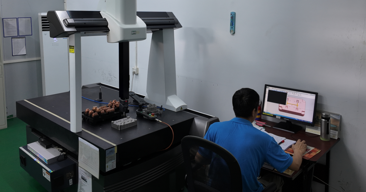
With a properly designed mold and consistent process control, our standard production achieves Series 1 (DIN 16901) tolerances as baseline on all engineering thermoplastics. Our precision molding capability — dedicated presses with closed-loop process control, Cpk monitoring per cavity, and in-house CMM inspection — supports Series 2 tolerances on amorphous materials and glass-filled engineering grades.
For parts requiring Series 3 tolerances, we conduct a moldability review of each critical dimension before quoting — assessing the material, geometry, wall thickness, gate location, and cooling layout to determine whether the tolerance is achievable and what tooling approach is required to deliver it.
The review is included with every quotation. Submit your toleranced drawing and we return a written assessment: which tolerances are achievable at standard production, which require premium tooling, and which — if any — require design modification.