IML and IMD — In-Mold Decoration for Graphics-Intensive Plastic Parts
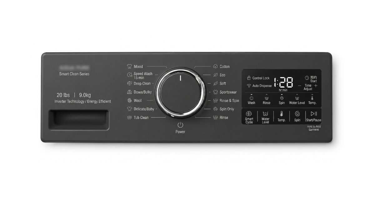
A product manager at an appliance brand approves the control panel design for a new washing machine. The panel is a 380 × 120 mm injection-molded ABS part with a dark grey background, white icons, and a chrome-look perimeter ring around the rotary dial. The decoration spec calls for pad printing. The tooling is built, the parts are molded, the decoration is printed.
Twelve months into production, the procurement team receives a field quality report: 4.7% of units are showing icon wear on the most-used buttons — the “start” and “temperature” icons are fading where fingers touch them repeatedly. The pad-printed ink is sitting on top of the ABS surface, bonded mechanically by surface roughness and a thin adhesion promoter. It is durable enough for a display unit at a trade show. It is not durable enough for 2,000 cycles of a wet finger pressing the same 8 mm circle every day for three years.
The fix is a process change, not a material change: move the decoration from the surface to inside the part. In-Mold Labeling (IML) embeds the graphic inside a multi-layer film that is placed into the mold cavity before injection. The molten plastic fuses with the film. The graphic is not on the surface — it is the surface. It cannot peel or wear off because there is nothing to peel: the decoration is the outermost 0.3–0.5 mm of the part, chemically fused to the substrate.
This guide compares IML and its variant IMD (In-Mold Decoration), explains the mold design requirements and material pairings, and provides the cost data to decide when in-mold decoration beats post-mold printing.
1. IML vs IMD vs IMR — Three Processes, One Principle
All three processes decorate the part during molding. The difference is what stays on the part and what leaves with the mold.
| Process | What Goes Into the Mold | What Stays on the Part | What Is Removed |
|---|---|---|---|
| IML (In-Mold Labeling) | Pre-printed multi-layer film, die-cut to shape | The entire film — graphic layer + protective top layer + bonding layer — fused to the part surface | Nothing |
| IMD (In-Mold Decoration) | Pre-printed film on a PET carrier | Only the ink/decoration layer — transferred to the part surface during molding | PET carrier film is peeled off after molding |
| IMR (In-Mold Roller) | Continuous roll of pre-printed film, indexed through the mold between shots | Only the ink layer — transferred from the moving film | Entire carrier film is rewound after transfer |
IML — The Film Becomes the Surface
IML starts with a flat, pre-printed film — typically 0.3–0.5 mm thick, multi-layer, with the graphic printed on the reverse side. The film is die-cut to the approximate contour of the part and placed into the mold cavity. Static charge or mechanical registration holds it in position. The mold closes, the plastic is injected, and the molten resin bonds with the back side of the film. The graphic is trapped between the clear top layer of the film and the injected substrate — permanently encapsulated.
IML produces the most durable result of the three processes. The film is a structural layer of the part, not a coating. It resists scratching (the graphic is under the protective top layer), chemicals (no adhesive interface to attack), and UV (the film absorbs UV before it reaches the graphic). A well-designed IML part can survive 10,000+ abrasion cycles — equivalent to the lifetime of an automotive interior switch or a medical device control panel.
IMD — The Ink Transfers, the Carrier Leaves
IMD uses a thinner film construction — a PET carrier, typically 0.05–0.125 mm, with the decoration printed on the side facing the injected plastic. The film is positioned in the mold. During injection, the heat and pressure of the melt transfer the ink from the carrier to the part surface. When the mold opens, the PET carrier is peeled away and discarded. The ink remains on the part, typically with a thin clear coat applied in a post-mold step for abrasion resistance.
IMD is thinner than IML and better suited to parts where the film edge must be invisible — the edge of an IML film is a 0.3 mm step on the part surface, which is visible and tactile. An IMD part has no film edge because only the ink transfers. The trade-off is durability: without the protective top layer of an IML film, the decoration is closer to the surface and more vulnerable to wear.
IMR — For High-Volume Continuous Production
IMR is the automated, high-volume variant. Instead of discrete die-cut films, IMR uses a continuous roll of film that advances through the mold between shots. A new section of film is indexed into position before each injection cycle. This eliminates the manual or robotic film placement step that IML and IMD require. IMR is used when the annual volume is measured in millions of parts — automotive interior trim, cell phone covers, appliance fascia panels. The tooling cost is higher due to the film indexing mechanism integrated into the mold, but the per-part labor cost is eliminated.
2. The IML Film — What It Is Made Of
An IML film is not a simple printed sheet. It is a multi-layer engineered structure:
| Layer | Function | Typical Material | Thickness |
|---|---|---|---|
| Protective top layer | UV resistance, scratch resistance, chemical resistance | UV-cured hard coat on PET or PC | 5–15 µm |
| Graphic/ink layer | The visible design — colors, text, icons | Solvent-based or UV-cured screen printing inks | 2–10 µm |
| Carrier/substrate layer | Mechanical body of the film, provides stiffness for handling | PET, PC, or PP — must match or be compatible with the injected resin | 200–400 µm |
| Bonding layer | Heat-activated adhesive that fuses with the injected melt | Co-polyester or co-polyolefin, formulated to match the substrate resin | 5–15 µm |
The critical rule for IML material pairing: the film carrier and the injected resin must be chemically compatible. A PP film bonds reliably to PP resin because they are the same polymer family — the melt fuses with the bonding layer, which is itself a PP-compatible co-polymer. A PC film and PC resin bond similarly. Mismatched pairings — a PP film with PC resin, or vice versa — produce weak adhesion at the film-substrate interface because the materials do not fuse; they simply cool next to each other.
The practical consequence: if the part is molded in PP, the film must be PP-based. If the part is molded in PC, the film must be PC-based. This limits the resin options for IML parts to materials with commercially available compatible films — PP, PC, ABS (with PC-compatible films), and to a lesser extent PA and PMMA. For a broader guide to resin selection across all injection molding applications, see our material comparison framework.
3. Mold Design for IML
An IML mold is not a standard injection mold with a film dropped in. It requires five DFM features that a standard mold does not:
Film positioning and retention. The die-cut film must be placed in the correct position and held there during mold closing and injection. The most common method is electrostatic charging — the film is charged with a static generator and clings to the grounded cavity surface. The static charge must be sufficient to hold the film against the 50–100 MPa injection pressure without shifting. If the film shifts, the graphic is misaligned on the part. Misalignment of more than 0.3 mm is typically visible and unacceptable on a consumer-facing part.
Gate location. The gate cannot be placed behind a decorated area of the film. The incoming melt at 230–300°C will wash away the ink at the gate impingement point. The gate must be positioned behind an undecorated area of the film — a border, a returning flange, or a hidden surface. For parts with full-surface decoration, this constraint drives the gate to the edge of the part, which can create fill balance issues that must be resolved in the mold design.
Venting for film-side air. When the film covers the entire cavity surface, trapped air creates venting challenges — the air between the film and the cavity steel has no escape path. When the film covers the entire cavity surface, the air between the film and the cavity steel has no escape path. As the melt fills the cavity and presses the film against the steel, trapped air creates bubbles or incomplete film adhesion. The mold must include venting channels on the cavity side — shallow grooves at the parting line or at the edges of the decorated area — to allow the air to escape as the film is pressed against the cavity.
Film edge termination. The edge of an IML film is a visible and tactile transition — 0.3–0.5 mm step from film surface to bare plastic. For parts where the film reaches the edge of the part, the film is typically wrapped around the edge and terminated on the back side or in a designed groove. For parts where the film stops before the edge, the transition line is a cosmetic feature that must be positioned intentionally — not left wherever the die-cut outline happened to fall.
Cooling balance. The film on one side of the cavity acts as a thermal insulator — 0.4 mm of PET has roughly the same insulating effect as 2–3 mm of steel. The cavity side with the film runs hotter than the core side without it — a cooling imbalance that must be compensated: the film side typically requires more aggressive cooling (more channels, closer standoff, higher flow rate) to maintain temperature balance and prevent differential cooling warpage.
4. Cost Comparison — IML vs Post-Mold Decoration
The comparison is not IML vs nothing. It is IML vs the alternative decoration method that achieves the same functional and cosmetic result.
| Cost Factor | IML | Pad Printing | Screen Printing | Painting + Laser Etch |
|---|---|---|---|---|
| Tooling cost adder | $1,500–4,000 (film positioning + venting) | $0 | $0 | $0 |
| Per-part decoration cost | $0.08–0.35 (film + placement) | $0.03–0.10 | $0.05–0.15 | $0.15–0.50 |
| Cycle time impact | +2–5 seconds (film placement) | 0 (offline) | 0 (offline) | 0 (offline) |
| Durability (abrasion cycles to failure) | 10,000+ | 500–2,000 | 1,000–5,000 | 5,000–20,000 |
| Chemical resistance | Excellent — no adhesive interface | Poor to moderate | Moderate | Good |
| 3D contoured surfaces | Yes — film can form to 3D geometry during molding | No — flat or simple curves only | No — flat surfaces only | Yes — but masking complex |
| Secondary operation | None — decoration is complete at mold opening | Yes — separate printing station | Yes — separate printing station | Yes — paint + laser |
| Multi-color registration | Excellent — all colors printed on film in one setup | Requires multiple fixtures, one per color | Requires multiple screens, one per color | Limited by laser masking |
The breakeven analysis for a mid-volume part — PP control panel, 380 × 120 mm, 3-color graphic, 80,000 parts per year, three-year production life:
- Pad printing: $0 (tooling) + 80,000 × 3 years × $0.07 = $16,800. One fixture per color = 3 fixtures at $400 each = $1,200. Total: $18,000. Durability: 1,500 cycles.
- IML: $2,500 (tooling adder) + 80,000 × 3 years × $0.22 = $158,400. Total: $55,300 over three years. Durability: 10,000+ cycles.
For a consumer panel that needs to survive 2,000 cycles, pad printing fails the durability requirement. The comparison is not cost — it is that one process meets the specification and the other does not. For a low-wear internal part, pad printing wins on cost at any volume. For a high-wear, cosmetic, or chemical-exposed surface, IML wins because the alternative does not survive the application.
5. When IML Is the Right Call
IML is the correct decoration method when three conditions are met simultaneously:
The decoration must survive the product lifetime. If the graphic will see repeated contact — fingers, cleaning chemicals, UV exposure, abrasion — and failure of the decoration is a warranty or brand-perception problem, IML or IMD is indicated. Pad printing on a car interior button fails at 30,000–50,000 km. IML on the same button looks the same at 150,000 km and at 0 km.
The decoration covers a significant area with multiple colors or fine detail. IML prints all colors in a single film manufacturing step — the registration between colors is determined by the screen printing setup on the film, not by part fixturing in a post-mold operation. If the graphic requires three colors with 0.2 mm registration tolerance between them, IML achieves this on the film. Pad printing requires the part to be re-fixtured three times, and each fixture adds ±0.1 mm of registration error.
The annual volume justifies the tooling investment. Below about 5,000 parts per year, the IML film tooling and mold modification costs do not amortize to a competitive per-part cost. Between 5,000 and 20,000 per year, the decision depends on the durability requirement. Above 20,000 per year and with a durability requirement beyond 5,000 cycles, IML is typically the economic choice.
IML is the wrong call when:
- The decoration is simple, single-color, and applied to a non-contact surface — pad printing or laser marking is cheaper and faster.
- The part volume is under 5,000 per year, and the durability requirement is modest — the tooling cost dominates the per-part cost.
- The part geometry has sharp internal corners or deep draws that the film cannot conform to without wrinkling. IML film can stretch approximately 5–10% before the graphic distorts visibly. A part with a 20 mm deep draw over a 10 mm radius will wrinkle the film.
- The production run involves frequent graphic changes. Changing an IML graphic requires a new film printing run and possibly a new die-cutting tool. Pad printing requires a new cliché plate — $100–300 and 2–3 days. For short runs with variant graphics, IML is too inflexible.
Frequently Asked Questions
What is the minimum text size IML can reproduce?
0.5 mm character height with 0.1 mm line width is achievable on a well-printed film. Below 0.4 mm, the ink tends to fill in small characters during molding due to melt pressure against the film. For regulatory text that must remain legible after molding, specify 0.6 mm minimum character height and confirm with a T1 sample.
Can IML be applied to a curved or 3D surface?
Yes — the film is flat when placed into the cavity, but it softens under the heat of the injected melt and conforms to the cavity surface as the cavity fills. Gentle 3D contours (draft angles of 5° or more, radii above 5 mm) form reliably. Deep draws, sharp corners, or undercuts will wrinkle or tear the film. The same part design rules that apply to draft angles and wall transitions apply to film formability. The film supplier provides a forming limit diagram that shows the maximum draw depth as a function of radius for a given film thickness.
How long does the IML film last before molding?
IML film has a shelf life of approximately 12 months when stored in sealed packaging at 15–25°C and 30–50% relative humidity. The limiting factor is the bonding layer — it is heat-activated, and exposure to humidity or high temperature can prematurely activate or degrade it, reducing bond strength during molding.
IML and IMD are the only decoration methods that make the graphic part of the part — not something applied on top and hoping it stays there. For a control panel that fingers will touch 10,000 times, a medical device that will see IPA wipes daily, or an automotive switch that must look the same after 150,000 km, in-mold decoration is the specification that meets the application. The mold costs more. The film costs more. The result — a part that leaves the mold decorated, with a graphic that lasts the life of the product — is the point.