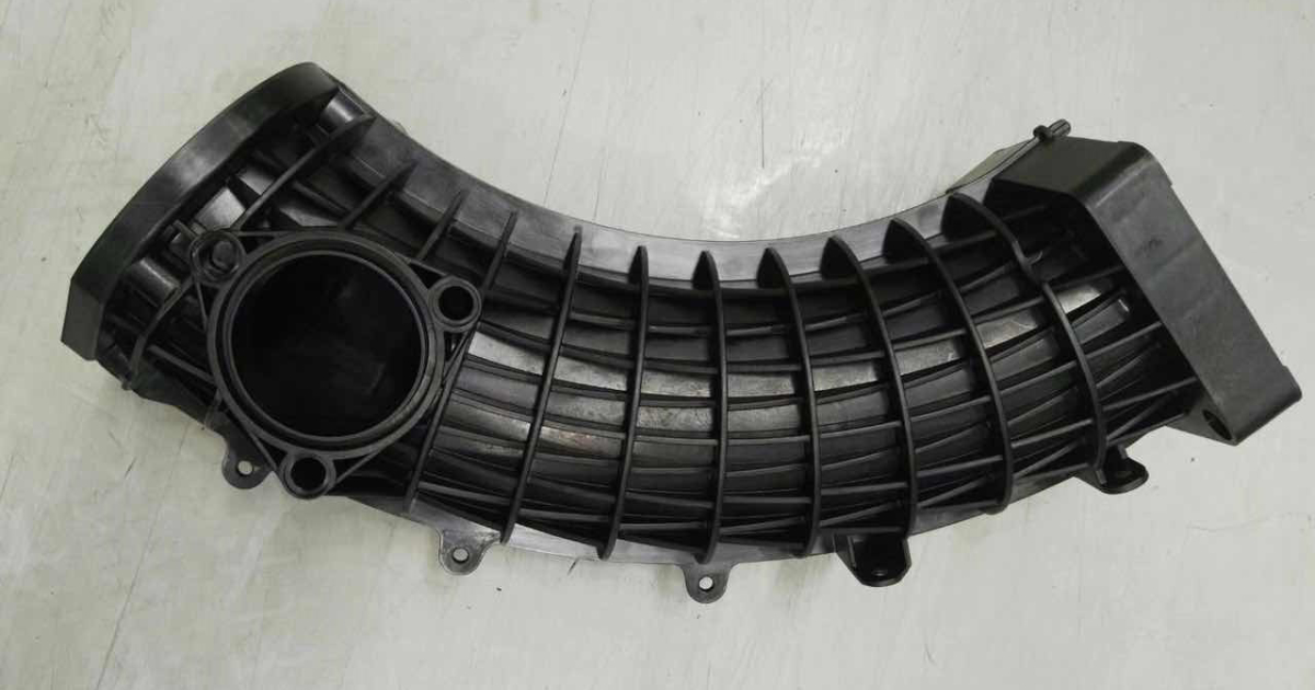
Glass-Filled Plastics in Injection Molding — When and How to Use Them
Adding glass fibre to a thermoplastic resin transforms it. Tensile strength doubles. Stiffness triples. Heat deflection temperature jumps 30–60°C. Shrinkage drops from 1.5% to 0.3%. And the mold wears out three times faster.
Glass-filled plastics are among the most widely used engineering materials in injection molding — and among the most misunderstood. A designer specifies PA66-GF30 because it is “stronger than unfilled nylon,” without understanding that the glass fibre has also made the material anisotropic, abrasive, and notch-sensitive. The part that comes out of the mold is not simply a stronger version of the unfilled part — it is a different material with different behaviour, and the design and tooling must account for that.
This guide covers what glass fibre reinforcement actually does, how to choose the right base resin and fibre loading for your application, and what changes in part design, mold design, and processing when you add glass.
What Glass Fibre Does
Glass fibre reinforcement changes a plastic in five ways — some beneficial, some challenging.
What Improves
| Property | Change (vs Unfilled) | Mechanism |
|---|---|---|
| Tensile strength | +50% to +150% | Fibres carry load in tension; polymer transfers load between fibres |
| Flexural modulus (stiffness) | +100% to +300% | Fibres resist bending; stiffnes proportional to fibre volume fraction |
| Heat deflection temperature (HDT) | +30°C to +60°C | Fibres maintain stiffness at temperatures where the polymer matrix softens |
| Shrinkage | Reduced by 50–80% | Fibres do not shrink; they constrain the polymer matrix as it cools |
| Creep resistance | Significantly improved | Fibres resist time-dependent deformation under continuous load |
What Gets Worse
| Property | Change (vs Unfilled) | Consequence |
|---|---|---|
| Elongation at break | Reduced by 80–95% | The material is stronger but more brittle — it snaps rather than yields |
| Impact strength (unnotched) | Reduced by 30–60% | Less energy absorbed before fracture |
| Notch sensitivity | Significantly increased | A sharp corner concentrates stress that fibres cannot redistribute |
| Weld line strength | Reduced by 30–50% | Fibres at the weld line are oriented parallel to the weld, not across it — no load transfer |
| Surface appearance | Fibre-rich surface, visible orientation | Cosmetic parts require additional processing (painting, film insert) or a different material |
The anisotropy problem: Glass fibres align with the direction of melt flow during injection. The resulting part is stiff and strong in the flow direction and weaker in the transverse direction. A PA66-GF30 part may have a tensile strength of 180 MPa in the flow direction and 110 MPa transverse — a 40% difference. Design assumptions based on isotropic material properties will overestimate transverse strength.
Common Glass-Filled Materials
PA66-GF30 (30% Glass-Filled Nylon 66)
The workhorse of glass-filled engineering thermoplastics.
| Property | PA66 Unfilled | PA66-GF30 |
|---|---|---|
| Tensile strength (MPa) | 80 (dry) | 180 (dry) |
| Flexural modulus (GPa) | 2.8 | 8.5 |
| HDT at 1.8 MPa (°C) | 75 | 250 |
| Elongation at break (%) | 25–40 | 2.5–3.5 |
| Mould shrinkage (%) | 1.0–2.0 | 0.3–0.8 |
| Density (g/cm³) | 1.14 | 1.38 |
Best for: Under-hood automotive brackets, structural housings, gears, fan blades, power tool bodies. Any application where high strength and stiffness at elevated temperature are required.
Limitations: Absorbs moisture — properties change between dry-as-molded and conditioned states. Weld lines are weak. Anisotropic — design for the weaker transverse direction. Higher density than unfilled PA66 means heavier parts.
PA6-GF30
Similar to PA66-GF30 but with lower HDT (210°C vs 250°C at 1.8 MPa) and slightly lower cost. Adequate for interior automotive, general industrial, and consumer applications where the 210°C HDT is sufficient. Processes at lower temperature than PA66 (240–270°C vs 270–300°C melt).
PBT-GF30
The standard material for electrical connectors and sensor housings.
| Property | PBT Unfilled | PBT-GF30 |
|---|---|---|
| Tensile strength (MPa) | 55 | 135 |
| Flexural modulus (GPa) | 2.5 | 9.0 |
| HDT at 1.8 MPa (°C) | 60 | 205 |
| Elongation at break (%) | 150 | 2.5–3.0 |
| Mould shrinkage (%) | 1.5–2.0 | 0.2–0.5 |
Best for: Electrical connectors, sensor bodies, ignition system components, relay housings. Excellent electrical properties and very low moisture absorption (0.1% vs 2.5% for PA66). Dimensional stability is excellent due to low moisture uptake and low shrinkage.
Limitations: Notch-sensitive. Degrades under hot water / steam exposure — not for autoclave sterilization. Lower impact than PA66-GF30.
PP-GF30
Glass-filled polypropylene — the budget engineering material.
| Property | PP Unfilled | PP-GF30 |
|---|---|---|
| Tensile strength (MPa) | 30 | 80 |
| Flexural modulus (GPa) | 1.2 | 5.5 |
| HDT at 1.8 MPa (°C) | 55 | 145 |
| Elongation at break (%) | > 100 | 3–5 |
| Mould shrinkage (%) | 1.5–2.5 | 0.3–0.6 |
Best for: Appliance components, HVAC ducts, automotive interior trim, washing machine parts. Cost-effective when you need dimensional stability and moderate strength but don’t need the high-temperature performance of PA66-GF30.
Limitations: Lower strength ceiling than glass-filled nylons. PP-GF30 is chemically a polypropylene matrix — any chemical that attacks PP will attack PP-GF30. Lower HDT than PA66-GF30 or PBT-GF30. Paint adhesion is poor without surface treatment.
PC-GF20 and PC-GF30
Glass-filled polycarbonate — high stiffness with PC’s inherent impact resistance. Used for precision structural components where PC’s notch sensitivity is a concern. PC-GF30 achieves flexural modulus around 8.0 GPa with significantly better impact than PA66-GF30 — but at higher material cost and with PC’s poor chemical resistance.
PPS-GF40
Polyphenylene sulphide with 40% glass fibre — for the highest-temperature injection molding applications. Continuous service temperature 200–240°C. HDT at 1.8 MPa > 260°C. Intrinsically flame retardant (UL94 V-0 without additives). Used for under-hood components in turbocharger areas, aerospace connectors, and semiconductor processing equipment.
Material cost is 5–10× PA66-GF30. Processing temperature is 320–340°C — requires hardened tooling with hot runner capable of sustained high-temperature operation. Not a general-purpose material.
Design Considerations for Glass-Filled Parts
Wall Thickness
Glass-filled materials can be molded thicker than their unfilled counterparts — 4.0mm is achievable without sink marks because the low shrinkage minimizes the differential cooling that causes sink. The practical upper limit is determined by cycle time, not material behaviour. Minimum wall thickness is higher than unfilled — 0.6mm minimum for PA66-GF30 versus 0.45mm for unfilled PA66 — because the glass fibres increase melt viscosity.
Draft Angles
Glass-filled materials shrink less, so they grip the core more tightly during ejection. Add 0.25°–0.5° to the draft angles recommended for the unfilled material. For PA66-GF30, specify 0.75° minimum where unfilled PA66 would use 0.5°.
Weld Line Management
Weld lines in glass-filled materials are structurally compromised. The fibres at the weld interface lie parallel to the weld plane — they do not cross the interface to transfer load. The weld line has approximately the strength of the unfilled polymer matrix, not the reinforced composite.
Mitigation strategies:
- Position the gate so that weld lines fall in low-stress areas
- Increase wall thickness at known weld line locations from 3mm to 4mm — the additional cross-sectional area compensates for the reduced material strength
- Use multiple gates or valve-gate sequencing to control where weld lines form
- Avoid weld lines in snap-fit beams, living hinges, or load-bearing ribs
Gate Design
Glass-filled materials are abrasive. The gate experiences the highest melt velocity in the entire flow path — and the highest erosion rate. Gate dimensions should be 10–20% larger than for the unfilled equivalent to slow the melt velocity and reduce gate wear. Gate inserts (replaceable steel inserts at the gate location) are standard practice for glass-filled production tooling above 100,000 shots — when the gate wears, the insert is replaced rather than the entire cavity.
Surface Finish
Glass-filled parts have a characteristic surface appearance: the glass fibres are visible at the surface, oriented in the direction of flow, creating a slightly textured, matte finish. This is inherent to the material — it cannot be polished away. Cosmetic glass-filled parts are either painted (automotive), covered with a film insert (appliance fascias), or specified in a colour that masks the fibre appearance (dark colours, textured surfaces).
If the part requires a Class A painted surface, the mold surface must be polished to SPI A-2 minimum — the smoother the mold surface, the smoother the paint finish. No amount of paint can hide a rough molding surface underneath.
Mold Wear with Glass-Filled Materials
Glass fibre is abrasive. Every shot scours the mold surface at the microscopic level — fibres scrape across the gate, the cavity wall, and the parting line. Over tens of thousands of cycles, this abrasion erodes the steel.
| Material | Relative Mold Wear Rate | Recommended Tool Steel |
|---|---|---|
| Unfilled PP, PE, ABS, PC | 1× (baseline) | P20 |
| PA66-GF30, PBT-GF30 | 3–5× | H13 hardened (48–52 HRC) minimum |
| PA66-GF50 | 5–8× | H13 hardened; consider D2 or carbide gate inserts |
| PPS-GF40 | 5–10× | H13 hardened; carbide gate inserts standard |
Where wear concentrates:
- The gate — highest melt velocity, highest erosion. Gate inserts recommended.
- Sharp corners — fibres impact the corner and deflect, scouring the steel at the impact point.
- The parting line — flash at the parting line erodes the shut-off surface, making flash progressively worse.
Compensating for wear in mold design:
- Specify hardened steel (H13 48–52 HRC) for all glass-filled production tooling. P20 is not adequate beyond prototype quantities.
- Use replaceable gate inserts so the highest-wear component can be refreshed without modifying the cavity.
- Increase shut-off land width at the parting line to provide more bearing surface for wear distribution.
- For programs above 500,000 shots, consider hard chrome or TiN coating on cavity surfaces in high-wear areas.
Processing: What Changes with Glass
Glass-filled materials process differently from their unfilled counterparts. The key differences:
- Higher melt temperature. The glass fibres increase thermal conductivity — more heat transfers into the material, requiring higher barrel temperatures to achieve the target melt temperature at the nozzle. Typically 10–20°C above the unfilled material’s processing range.
- Higher injection pressure. Glass-filled melts are more viscous — the fibres resist flow. Injection pressure is typically 20–40% higher than for the unfilled equivalent.
- Faster cooling. The glass fibres conduct heat away from the melt more efficiently. Cycle time may be slightly shorter — but the mold must be cooled more aggressively to maintain the same mold surface temperature, because more heat enters the steel per unit time.
- Screw and barrel wear. Glass fibres abrade the screw and barrel over time. Screws with hard-facing (Colmonoy, chrome plating, or bimetallic construction) are standard for glass-filled production. A standard nitrided screw used for unfilled materials will wear at 3–5× the rate on glass-filled production.
Frequently Asked Questions
What does GF30 actually mean?
GF30 means the material is 30% glass fibre by weight. A 70% polymer, 30% glass fibre compound. By volume, the glass fraction is lower — roughly 15–18% — because glass fibre (density ~2.54 g/cm³) is denser than the polymer matrix. Higher glass loadings (GF40, GF50) increase strength and stiffness further but reduce elongation and increase mold wear rates.
Can I use a glass-filled material as a drop-in replacement for the unfilled version?
No. The part design, mold design, and process parameters developed for the unfilled material will not transfer directly. The glass-filled material shrinks less — cavity dimensions must be re-cut. The glass-filled material wears the mold faster — steel grade must be upgraded. The glass-filled material has lower elongation — snap-fits and press-fits designed for the unfilled material may fail. Converting from unfilled to glass-filled requires a mold design review and likely tooling modification.
Do glass fibres affect recyclability?
Glass-filled thermoplastics can be reground and reprocessed, but the regrind has shorter fibre length than virgin material — the fibres break during molding and regrinding. Mechanical properties degrade with each regrind cycle. Typical practice limits regrind to 20–30% of the shot weight for non-appearance, non-safety-critical parts. For automotive PPAP and medical device programs, regrind use must be specifically approved by the customer.
Is glass-filled always the right choice for strength?
Not always. Glass fibre increases tensile strength and stiffness — but it reduces impact strength and elongation. If your part requires impact resistance more than stiffness (a protective housing that must survive a drop test), an unfilled PC or PC/ABS may outperform PA66-GF30 — despite the lower tensile strength on the datasheet. The right material depends on the specific loading condition, not the highest number on the spec sheet.
What is the difference between short glass fibre and long glass fibre?
Short glass fibre (SGF) — fibre length 0.2–0.5mm in the molded part. Standard for injection molding. Long glass fibre (LGF) — initial pellet fibre length 10–12mm, molded part fibre length 2–5mm. LGF materials provide higher stiffness and impact strength because longer fibres transfer load more effectively — but they are harder to process, more expensive, and produce a rougher surface finish. LGF is used for structural automotive and industrial components where the performance gain justifies the higher material cost and processing complexity.
Glass fibre reinforcement is one of the most effective tools in the plastics engineer’s kit — but it is not free. You pay for the improved strength and stiffness with increased brittleness, higher mold wear, anisotropic properties, and a surface finish that will never look like unfilled material. The specification decision — which base resin, which glass loading — should be driven by the specific functional requirements of the part, not by the highest numbers on a datasheet.
Material data: property tables for the common engineering and commodity resins in the injection molding materials guide →.
Submit your part for a free DFM review and material recommendation →