Gate Design Guide for Injection Molds — Types, Placement, and Vestige Management
A mold designer at a contract manufacturer receives a part file for a transparent polycarbonate medical device housing: 85 × 55 × 22 mm, 2.0 mm wall, polished SPI A-1 finish on all visible surfaces, and a specification note that reads “no gate vestige visible on any Class A surface.” The part has four exterior faces, all cosmetic. The bottom face is a snap-fit engagement surface with 12 cantilever features — functionally loaded, not available for a gate location. The internal surface is dotted with PCB standoffs, snap towers, and a battery compartment wall.
The designer has two questions that determine everything downstream: where does the gate go, and what type of gate can deliver the required cosmetic result while filling a 2 mm wall across an 85 mm flow length?
Gate design is the intersection of mold engineering, material behavior, and cosmetic requirements. A poorly chosen gate location produces a weld line through a structural feature. A poorly chosen gate type leaves a vestige that exceeds the cosmetic specification. A gate that is too small increases fill pressure, extends cycle time, and can shear-degrade the material at the gate entry point. This guide covers the five gate types used in production injection molds, the placement rules that determine fill quality, and the vestige management standards that cosmetic parts demand.
What the Gate Does
The gate is the final restriction through which molten plastic enters the mold cavity. It is the smallest cross-section in the entire melt delivery system — intentionally. The gate serves four functions:
- Flow restriction — Creates shear heating at the cavity entry point, reducing melt viscosity just as the material enters the cavity. This is the same principle as rubbing your hands together to warm them: the shear rate through the narrow gate generates frictional heat that improves flowability precisely where it is needed.
- Freeze-off control — The gate is the first point to freeze when injection stops, sealing the cavity from the runner system. If the gate is too large, the cavity can backflow into the runner when injection pressure drops — producing voids, sink marks, and dimensional variation.
- Vestige location — The gate leaves a witness mark on the part. The gate type determines the size, shape, and location of that witness mark. Cosmetic specifications drive gate selection as much as filling requirements do.
- Degating method — How the gate separates from the part after molding determines whether degating is automatic (the mold does it during ejection), manual (an operator cuts it), or robotic (a sprue picker or end-of-arm tool). The degating method directly affects per-part cost.
Gate Types — Selection by Geometry and Requirement
1. Edge Gate (Side Gate)
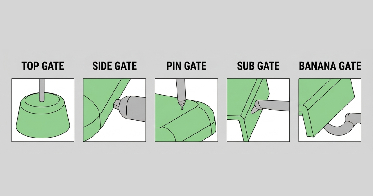
The most common gate type. A rectangular or trapezoidal cross-section cut into the parting line, feeding the cavity from one side. The gate is in the same plane as the parting line and feeds directly into the cavity wall.
| Parameter | Typical Value |
|---|---|
| Gate width | 1.5–6.0 mm (typically 0.5–0.8× part wall at gate location) |
| Gate depth | 0.5–1.5 mm (typically 0.5–0.7× part wall thickness) |
| Gate land length | 0.5–1.5 mm (short land = less pressure drop, more difficult to machine) |
| Draft on gate | 2–3° on each side for clean ejection |
When to use: General-purpose gate for parts where the gate vestige can be on a non-cosmetic edge. Works with almost all materials and part geometries. The rectangular cross-section provides a wide, shallow melt entry that distributes the flow front evenly along the cavity wall — reducing jetting and producing a smooth fill pattern.
When not to use: When the part has cosmetic requirements on all exterior faces, or when the gate location is on a surface visible to the end user. Edge gates leave a rectangular vestige that requires manual trimming — an operator cuts the gate remnant with flush cutters and the cut surface must be within the cosmetic specification.
Degating: Manual — an operator trims the gate vestige after ejection. Trim time is typically 3–8 seconds per part depending on gate dimensions and accessibility. For high-volume production, the cumulative labor cost of manual degating often justifies the higher tooling cost of an automatic-degating gate type.
2. Submarine Gate (Tunnel Gate / Sub Gate)
A conical or trapezoidal tunnel machined at an angle through the mold steel, entering the cavity below the parting line. The gate is torn from the part automatically during ejection — the angled tunnel shears the gate at the cavity wall as the part is ejected, separating the part from the runner without operator intervention.
| Parameter | Typical Value |
|---|---|
| Gate diameter at cavity | 0.5–1.8 mm |
| Tunnel angle | 30–45° from horizontal |
| Tunnel length | 1.5–4.0 mm |
| Gate entry location | 0.5–1.0 mm below parting line on cavity side wall |
When to use: High-volume production where manual degating cost is unacceptable. Submarine gates enable fully automatic molding — the part and runner eject separately, the runner drops into a collection bin, and the parts are conveyed to the next operation with no operator handling at the press. Particularly effective for PP, PE, and flexible materials that would be difficult to trim cleanly with an edge gate.
When not to use: Rigid, brittle materials (PS, unfilled POM, some grades of PMMA) that fracture rather than shear at the gate during ejection — the gate tear can propagate into the part body, creating a crack or a structural weak point. Glass-filled materials accelerate tunnel wear — the abrasive filler erodes the tunnel entry edge over 50,000–100,000 shots, requiring insert replacement. Also unsuitable for parts where the gate vestige (a small raised nub at the entry point) is on a cosmetic surface.
Degating: Automatic — sheared during ejection. The vestige is a small raised bump or depression at the gate entry point, typically 0.2–0.5 mm in height. Acceptable for internal surfaces and hidden external walls; not acceptable for Class A cosmetic surfaces.
3. Fan Gate
A gate that widens from the runner in a triangular or fan-shaped pattern, entering the cavity along a broad front. The gate depth is constant, but the width expands to distribute the melt over a wider cavity entry area.
| Parameter | Typical Value |
|---|---|
| Gate width at cavity | 6–40 mm (typically 2–10× the gate land depth) |
| Gate depth | 0.3–1.0 mm (thinner than the part wall at the entry point) |
| Fan angle | 15–30° total included angle |
| Gate land length | 0.5–1.5 mm |
When to use: Large, flat parts where a single point gate would produce excessive fill time and pressure drop. The wide melt entry produces a uniform flow front that reduces the risk of flow marks (record-groove effect) on visible flat surfaces — common in display bezels, appliance panels, and transparent parts where flow marks are a primary cosmetic defect.
When not to use: Small parts (the fan gate width would exceed the part dimension), multi-cavity tools where the fan gates would consume excessive mold real estate, or parts with complex geometry at the entry edge where the wide melt front would create unpredictable filling behavior.
Degating: Manual — requires trimming along a wide gate line. The wider the gate, the more operator time per part. For a 30 mm wide fan gate, trim time is 8–12 seconds compared to 3–5 seconds for a 4 mm edge gate. Fan gates are generally limited to single-cavity or low-cavitation molds where the degating labor does not dominate the per-part cost.
4. Diaphragm Gate (Ring Gate)
A full-circumference gate used for cylindrical parts where the melt enters around the entire perimeter of the part. The gate forms a thin annular ring that feeds the cavity from 360° simultaneously.
| Parameter | Typical Value |
|---|---|
| Gate land thickness | 0.2–0.5 mm |
| Gate land length | 0.5–1.0 mm |
| Runner type | Cold runner with annular feed ring |
When to use: Cylindrical or rotationally symmetric parts — gears, bearing retainers, lens housings, valve bodies, and any round part where concentricity is critical. The 360° melt entry produces perfectly radial flow, eliminating the warpage caused by asymmetric filling that a single edge gate creates on a round part. Also used for thin-wall cylindrical parts (wall <1.0 mm) where the 360° gate minimizes flow length and reduces fill pressure.
When not to use: Non-cylindrical parts (the geometry does not support an annular gate), or parts where the gate vestige around the entire circumference is unacceptable — the diaphragm gate leaves a thin annular witness line that must be trimmed or machined off.
Degating: Manual or machined. The thin annular gate is typically punched out in a secondary trimming operation (a punch and die set removes the gate ring in a single press stroke) or machined on a lathe for tight-tolerance requirements. Some designs incorporate an internal diaphragm gate (feeding into the center of a ring-shaped part) that is broken out by an ejector sleeve during ejection.
5. Valve Gate (Hot Runner Valve)
A hot runner gate with a mechanically actuated pin that opens and closes the gate orifice at the cavity surface. The pin is retracted by pneumatic or hydraulic pressure to allow melt flow during injection, then driven forward to seal the gate at the cavity surface when the cavity is filled. The result is a gate vestige that is nearly flush with the part surface — a flat, circular witness mark rather than a protruding nub.
| Parameter | Typical Value |
|---|---|
| Gate diameter | 1.5–6.0 mm (with the valve pin fully retracted) |
| Pin diameter | 1.0–4.0 mm (matches gate orifice) |
| Actuation | Pneumatic (standard) or hydraulic (for high-melt-temperature materials) |
When to use: Cosmetic parts where no raised gate vestige is acceptable — automotive interior trim, consumer electronics housings, medical device enclosures, and any Class A surface where the gate witness is on a visible face. Also used for large shot weights (>200 g) where the gate must remain open through an extended filling and packing phase, and for sequential valve gating where multiple valve gates open in sequence to control the filling pattern in large parts (automotive bumpers, instrument panels).
When not to use: Low-volume production where the hot runner system cost ($3,000–8,000 per valve gate drop) is not amortized over sufficient units. Materials that are thermally sensitive and would degrade in the hot runner manifold over extended residence time. Parts smaller than approximately 20 g where the valve gate hardware is physically too large for the cavity geometry.
Degating: None required — the valve pin seals the gate flush or nearly flush with the cavity surface. The gate vestige is a flat circular witness line, typically 0.02–0.05 mm deep, that can be specified as acceptable even on visible surfaces when positioned intelligently.
Gate Placement — The Five Rules
Gate placement is as important as gate type. A correctly designed gate in the wrong location produces a part that fills, but does not function.
Rule 1: Gate Into the Thickest Section
Plastic flows from thin to thick reluctantly and from thick to thin naturally. The gate should feed into the thickest section of the part so the melt front progresses from thick to thin — this ensures that the thin sections are the last to fill, which is what you want, because thin sections freeze fastest. If the gate feeds a thin section and the melt must flow into a thicker region, the thin section freezes before the thick section is fully packed, producing sink marks and voids in the thick zone.
For a part with variable wall thickness, locate the gate at the thickest wall and let the flow path progress to progressively thinner sections.
Rule 2: Position Weld Lines Deliberately
Every hole, slot, or core pin in the cavity creates a weld line downstream. The weld line position is predictable — it forms where the melt front recombines after being split by an obstruction. The designer controls where weld lines form by positioning the gate relative to the obstruction.
If a weld line must exist, place it:
- On a non-cosmetic surface (internal rib, hidden wall)
- Away from structural features (bosses, snap-fits, hinge points)
- Away from threaded insert locations where reduced strength at the weld would cause pull-out failure
Mold flow analysis software predicts weld line locations before steel is cut. A mold designer who skips this step discovers weld lines on the T1 sample and then has to explain to the customer why a visible line runs through the logo on the front face of the part.
Rule 3: Minimize Flow Length
The flow length from gate to the farthest cavity extremity determines the required injection pressure and the minimum wall thickness that can be filled. For a given material and wall thickness, there is a maximum flow length beyond which the melt front freezes before reaching the cavity end — producing a short shot.
| Material | Max Flow Length Ratio (flow length : wall thickness) |
|---|---|
| PP (easy flow) | 250:1 – 300:1 |
| ABS | 150:1 – 200:1 |
| PC | 80:1 – 120:1 |
| PC/ABS | 100:1 – 150:1 |
| PA6 | 150:1 – 250:1 |
| PBT | 100:1 – 150:1 |
| POM | 100:1 – 180:1 |
| PEEK | 50:1 – 80:1 |
If the required flow length exceeds the material’s capability at the given wall thickness, the options are: increase wall thickness (if design allows), move the gate closer to the far extremity (reducing flow length), or add additional gates (splitting the flow into shorter segments, at the cost of additional weld lines).
Rule 4: Avoid Direct Impingement on Cores
Gating directly opposite a core pin forces the melt to impinge on the pin surface at high velocity, creating a flow mark (splay or blush) radiating outward from the impingement point. The fix: offset the gate by at least 2× the gate diameter from the centerline of any core pin, or use a tab gate that redirects the melt flow parallel to the pin surface rather than perpendicular to it.
Rule 5: Account for Material-Specific Behavior
- Glass-filled materials (PA6-GF30, PP-GF20, PBT-GF30): Glass fiber orientation follows flow direction. A gate that produces asymmetric flow (single edge gate on a rectangular part) creates asymmetric fiber orientation, which produces differential shrinkage in the flow and transverse directions — and consequent warpage. A center gate or dual side gates that produce symmetric flow minimize post-molding warpage in filled materials.
- Flame-retardant materials: FR additives increase melt viscosity and reduce thermal stability. Larger gates (1.2–1.5× the standard gate cross-section for the same wall thickness) reduce shear heating and prevent material degradation at the gate. Smaller gates with FR materials produce burn marks at the gate within the first 100–200 shots.
- Transparent materials (PC, PMMA, MABS): Gate vestige is more visible than on pigmented materials. Submarine gates on transparent parts leave an internal stress concentration visible as a birefringence halo under polarized light. Edge gates on a non-cosmetic edge are the safest default for transparent parts unless a valve gate is justified by production volume.
Gate Size — The Cross-Section Calculation
A gate that is too small causes shear degradation (material burns at the gate), excessive pressure drop (higher clamp force requirement), and jetting (the melt shoots into the cavity as a narrow stream rather than a smooth front). A gate that is too large extends cycle time (the gate freezes more slowly, delaying screw recovery), leaves a larger vestige, and in a cold-runner system means a heavier runner that wastes material.
The starting point for gate depth and width is the part wall thickness at the gate location:
| Material | Gate Depth | Gate Width |
|---|---|---|
| ABS, PS, PMMA (amorphous, easy flow) | 0.5–0.7× wall | 0.5–1.0× depth |
| PC, PPO (amorphous, viscous) | 0.7–0.8× wall | 0.5–1.0× depth |
| PP, PE (semicrystalline, easy flow) | 0.4–0.6× wall | 0.8–1.2× depth |
| PA6, PA66 (semicrystalline, moderate) | 0.6–0.8× wall | 0.5–1.0× depth |
| POM, PBT (semicrystalline, moderate) | 0.6–0.8× wall | 0.5–0.8× depth |
| Glass-filled (>20%) | 0.8–1.0× wall | 0.6–0.8× depth |
| PEEK, PPS, PEI | 0.8–1.0× wall | 0.6–0.8× depth |
For a 2.0 mm ABS part wall at the gate location: gate depth = 1.0–1.4 mm, gate width = 0.5–1.4 mm. A gate depth of 1.2 mm and width of 1.0 mm is a conservative starting point that can be adjusted based on T1 fill results.
The gate land length — the distance from the runner to the cavity through which the gate cross-section is constant — should be as short as machinability allows, typically 0.5–1.5 mm. A shorter land reduces the pressure drop through the gate and the shear heating of the material. A longer land increases pressure drop and shear heating but provides a cleaner break point for submarine gates. The land length is a machining parameter, not a design parameter — the designer specifies the minimum practical value for the gate type and lets the mold maker determine what their EDM or CNC process can achieve.
Gate Vestige by Cosmetic Class
Cosmetic specifications define what degree of gate witness is acceptable:
| Cosmetic Class | Gate Vestige Requirement | Acceptable Gate Types |
|---|---|---|
| Class A (visible, no witness) | Flush to 0.05 mm max, no raised nub | Valve gate only |
| Class B (visible, minor witness OK) | Raised witness ≤0.2 mm, flat cut surface | Submarine gate (non-cosmetic face), trimmed edge gate |
| Class C (non-visible or hidden) | Witness ≤0.5 mm, cut mark acceptable | Edge gate, submarine gate, fan gate |
| Internal (function-only) | No restriction | Any gate type |
For the medical device housing that opened this guide — Class A on all exterior faces, internal surface loaded with functional features — the gate solution is a valve gate on the internal surface. The valve pin enters from the core side (internal cavity surface), positioned between the PCB standoffs where it leaves a 0.02 mm deep circular witness on a non-cosmetic internal face. The hot runner system adds $5,000 to the mold cost but avoids manual degating and cosmetic rejects — the alternative of an edge gate on the bottom snap-fit edge would have required manual trimming of 12 gates per part at an estimated 18 seconds of operator time per part, adding approximately $0.45 per part in labor cost. At 50,000 units per year, the valve gate pays back the hot runner investment in the first year of production and produces a cosmetically superior part.
Gate design is not an afterthought in the mold design process. It determines fill quality, controls weld line position, sets the cosmetic standard for the part, and defines the per-part degating cost that accumulates across every production run for the life of the mold. The time spent determining the gate type and position is repaid in the avoidance of one tooling modification to relocate a gate that was placed without considering Rule 2: position weld lines deliberately.