Gas-Assisted Injection Molding — A Technical Guide for Hollow and Thick-Walled Plastic Parts
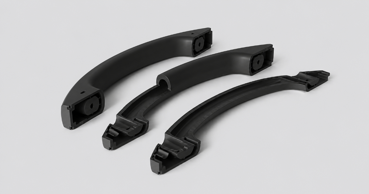
A product engineer at an automotive supplier is designing an interior door grab handle. The current design is a solid ABS part — 180 mm long, 28 mm in diameter at the grip, with 4 mm nominal wall thickness and four mounting bosses. At 50,000 units per year, the cycle time is 42 seconds. The part weighs 85 grams. Every boss junction shows a visible sink mark through the painted Class A finish. The OEM has rejected the last three PPAP submissions for cosmetic defects at the boss locations. The tooling team has maxed out the packing pressure, increased the hold time, and tried three different material grades. Nothing eliminates the sink marks without extending the cycle time beyond the quoted cost envelope.
The solution is not more packing pressure. It is nitrogen gas.
The Problem: When Solid Plastic Is Too Much
A plastic part with a 20 mm cross-section sounds like a straightforward injection molding job — until you run the numbers. The cooling time for a 20 mm solid section is roughly proportional to the square of the wall thickness. At 2 mm wall, cooling takes 5–8 seconds. At 20 mm, it takes 8–12 minutes. That is not a cycle time that works in a production environment.
Even if you could wait, the part would develop a deep sink mark at every thick section junction. As the molten core cools and shrinks, the already-solidified skin gets pulled inward — producing a visible depression that no amount of packing pressure can prevent. Increasing packing pressure to compensate creates internal stress that warps the part during ejection.
This is where gas-assisted injection molding enters the conversation.
Take a chair armrest, an automotive door handle, or an appliance grab bar. These parts need structural rigidity — a solid cross-section would consume unnecessary material, extend cycle time to economically unviable levels, and produce cosmetic defects at every junction. Gas-assisted molding solves all three problems simultaneously: it hollows out the thick section with pressurized nitrogen, reducing material by 20–40%, cooling time by 40–60%, and sink marks to zero.
What Is Gas-Assisted Injection Molding?
Gas-assisted injection molding is a process variant where pressurized nitrogen gas (typically 200–350 bar) is injected into the mold cavity during or immediately after the plastic melt injection. The gas follows the path of least resistance through the molten core of the part, displacing plastic outward against the cavity wall and creating a network of hollow channels throughout the thick sections.
The gas does not mix with the plastic — it pushes the still-molten core material forward, completing the cavity fill while simultaneously hollowing the interior. The result is a part with a solid skin and a hollow core, structurally similar to a bone or a hollow tube: maximum bending stiffness for minimum material weight.
Two process variants dominate industrial practice:
Short-Shot Process (Internal Gas Molding)
The mold cavity is intentionally filled to only 70–85% of its total volume with plastic melt. Nitrogen gas is then injected through a gas pin directly into the molten plastic. The gas expands, pushing the plastic outward until it contacts the entire cavity wall. Because the gas injection compensates for the intentionally short plastic shot, the final part is fully formed — but with a hollow core rather than solid cross-section.
The short-shot method is the most widely used variant. It works best for parts with clearly defined thick sections that can serve as gas channels — handles, rails, frames, and components with a single dominant flow path.
Full-Shot Process (External Gas Molding)
In full-shot molding, the cavity is completely filled with plastic melt — a standard injection cycle. Gas is then introduced on the non-appearance side of the part, typically through gas pins positioned opposite cosmetic surfaces. The gas does not penetrate the part interior but instead applies uniform pressure to the surface, packing the plastic against the cavity from the outside while the core cools.
External gas molding is primarily used for sink mark elimination on large flat surfaces and ribbed structures — appliance fascias, dashboard panels, and consumer electronics housings where cosmetic requirements preclude any surface defect. The gas pressure, maintained throughout the cooling phase, prevents the plastic skin from pulling away from the cavity surface as the core shrinks.
The Physics: Why Gas Does What Packing Pressure Cannot
Conventional injection molding relies on the plastic melt itself to transmit packing pressure from the screw through the gate, through the runner, through thin walls, and into thick sections. But plastic is a poor hydraulic fluid — its viscosity increases exponentially as it cools, and the pressure drop along the flow path means that a thick section 150 mm from the gate may see only 15–20% of the packing pressure applied at the screw.
Gas has no such limitation. Nitrogen at 300 bar experiences negligible pressure drop over any distance within a mold. Once the gas channel forms, the pressure is uniform throughout the entire gas network. A thick section 200 mm from the gate sees exactly the same packing pressure as one 20 mm from the gate.
This uniform pressure delivery is the fundamental reason gas-assisted molding eliminates sink marks. Every cubic millimeter of the part’s interior is held at identical pressure until the skin solidifies. There are no low-pressure zones where shrinkage can pull the surface inward.
When to Use Gas-Assisted Molding: The Decision Matrix
Not every thick-walled part needs gas assist. The decision depends on the specific geometry and economic equation.
Ideal Candidates
| Geometry Type | Why Gas Wins | Examples |
|---|---|---|
| Solid handles and grips | Eliminates sink at junctions, reduces material 25–35% | Chair armrests, tool handles, appliance grips |
| Long structural rails | Continuous gas channel replaces solid rib, cuts weight 30–40% | Automotive roof rails, conveyor guides |
| Large panels with rib grids | External gas packs ribs without sink marks on face side | Dashboard panels, furniture tops, appliance doors |
| Thick-to-thin transitions | Gas distributes pressure uniformly across section changes | Pump housings, manifold covers |
| Multi-boss components | Gas channels connect isolated thick sections, uniform packing | Equipment frames, medical device housings |
When Conventional Molding Is Better
| Condition | Reason |
|---|---|
| Uniform wall thickness <3 mm | No thick sections for gas to follow — process adds cost with no benefit |
| High cosmetic requirements at gas pin locations | Gas pins leave a small witness mark — unacceptable on Class A visible surfaces |
| Transparent parts | Gas channel creates visible internal void — optical clarity degraded |
| Small shot volumes (<5,000/yr) | Gas assist equipment amortization exceeds material and cycle time savings |
| Parts requiring uniform density | Some structural applications need solid cross-sections for load distribution |
Material Selection for Gas-Assisted Molding
Most injection molding thermoplastics are compatible with gas-assisted processing, but the process imposes specific requirements that narrow the practical material selection:
Ideal materials:
- PP (Polypropylene): The most commonly gas-assisted material. Low melt viscosity allows gas to penetrate long distances (600+ mm gas channels are feasible). Wide processing window tolerates the gas injection cycle. Excellent for furniture, appliance, and automotive interior applications.
- ABS: Good gas penetration characteristics. Smooth internal channel surfaces. Well-suited for painted and electroplated parts where sink marks must be eliminated.
- HDPE: Similar to PP in gas-processing behavior. Used for large structural containers, pallets, and outdoor furniture.
- PA 6/66 (Nylon): Higher viscosity than PP but manageable with elevated melt temperatures. Used for automotive underhood components where heat and chemical resistance are required.
Materials requiring process adjustment:
- PC (Polycarbonate): High melt viscosity limits gas penetration distance. Requires higher gas pressure (250–350 bar) and elevated melt temperature. Gas channel surface can show internal roughness.
- PC/ABS blend: Better gas-processing behavior than pure PC. Used for painted electronic housings and appliance panels.
- POM (Acetal): Gas-processable but requires careful temperature control. Degradation at processing temperatures can produce formaldehyde gas — ventilation and process monitoring are required.
- Glass-filled grades: Abrasive to gas pins and require hardened pin components. Gas penetration distance is reduced because the glass fibers increase melt viscosity.
Materials to avoid:
- LCP (Liquid Crystal Polymer): Highly anisotropic melt flow — gas follows unpredictable paths, making channel geometry uncontrollable.
- TPE/TPU: Elastic melt behavior makes gas channel formation inconsistent. Gas can “worm” through the soft melt rather than forming a clean channel.
Design Guidelines for Gas Channel Geometry
The gas channel is the engineered void that carries nitrogen through the part. Its design determines whether the process works or fails.
Channel Sizing
The gas channel diameter should be 2–3× the adjacent nominal wall thickness. For a part with 3 mm walls, the gas channel cross-section should be 6–9 mm in diameter. Below 2× wall thickness, the gas flows preferentially through the thinner wall sections rather than staying contained within the designated channel — this produces uncontrolled gas breakthrough to the part surface, a defect commonly called “fingering.”
The gas channel should be continuous and uninterrupted from the gas injection point to the end of the thick section. Dead-end channels, where gas can enter but not flow through, create pressure imbalances — the gas compresses in the dead end but cannot distribute packing pressure to adjacent sections.
Gas Pin Placement
Gas pins should be located in non-appearance surfaces wherever possible — the underside of a handle, the back face of a panel, or an internal rib surface. The gas pin leaves a small witness mark (typically 1.0–2.0 mm diameter) that is visible on textured surfaces and conspicuous on high-gloss finishes.
For parts with multiple thick sections separated by thin walls, multiple gas pins may be required — one per isolated thick section. A single gas pin cannot pressurize a thick section that is physically disconnected from the gas channel network.
Overmolding and Multi-Material Compatibility
Gas-assisted molding can be combined with overmolding, but the gas channel must be fully contained within the substrate material. If the gas channel intersects the bond line between substrate and overmold, the pressurized gas can delaminate the two materials at the interface.
Equipment and Setup Requirements
Gas-assisted molding requires two additional system components beyond a standard injection molding machine:
Nitrogen generation and compression module. The system takes ambient air, strips out oxygen and moisture through a membrane or PSA (pressure swing adsorption) unit, and compresses the remaining nitrogen to 200–350 bar. A typical module provides 99.5% nitrogen purity at flow rates sufficient to deliver gas volumes of 2–50 cm³ per shot, depending on the channel geometry.
Gas injection control unit. The controller regulates gas pressure, gas volume, injection timing, and pressure decay profile during the cooling phase. Most modern controllers provide multi-stage pressure profiles — an initial high-pressure phase (250–350 bar) to establish the gas channel, followed by a lower holding pressure (100–200 bar) during cooling to prevent over-packing.
The gas is introduced through a gas pin installed directly in the mold, connected to the control unit via high-pressure stainless steel tubing. Gas pins are available in two configurations: fixed pins (direct-mount in the mold) for simple geometries, and retractable pins (retracted after gas injection for a clean surface) for appearance-critical applications.
Process Parameters
| Parameter | Typical Range | Notes |
|---|---|---|
| Gas pressure (initial) | 200–350 bar | Higher for viscous materials (PC, PA) |
| Gas pressure (holding) | 100–200 bar | Prevents over-packing during cooling |
| Gas delay time | 0.5–3.0 s | After plastic injection; shorter for thin walls |
| Gas injection time | 1.0–5.0 s | Until channel fully formed |
| Gas hold time | 10–30 s | Until gate freeze-off |
| Melt shot volume | 70–85% of cavity | Short-shot method; 100% for external gas |
| Melt temperature | Material standard | May increase 5–10°C for gas penetration |
| Nitrogen purity | ≥99.5% | Oxygen degrades polymer and causes burn marks |
The gas delay time — the interval between the end of plastic injection and the start of gas injection — is the most sensitive timing parameter. A mold flow analysis simulation can predict the optimal delay window before cutting steel, reducing T1 tuning iterations by 2–3 cycles. Too short, and the gas blows through the melt before a stable skin forms, producing surface breakthrough. Too long, and the skin is too thick for the gas to displace the core material, producing incomplete channel formation. The window is typically 0.5–3.0 seconds, depending on material thermal diffusivity and wall thickness.
Quality Control for Gas-Assisted Parts
Gas-assisted parts introduce QC requirements beyond conventional molding:
- Channel continuity. X-ray or ultrasonic inspection of gas channels on first-article samples to verify that channels are continuous, correctly positioned, and free of isolated voids — integrated into the production QC protocol. Cross-section cutting on 1:500 samples confirms channel diameter and wall thickness distribution.
- Surface inspection. Visual inspection under 800 lux for gas breakthrough (“fingering”), surface blistering, and gas pin witness marks. Gas pin locations are high-risk areas — the pin orifice can clog or wear, producing inconsistent gas injection.
- Weight verification. Gas channel volume is directly reflected in part weight. Weight variation exceeding ±1.5% indicates inconsistent gas penetration — either incomplete channel formation (heavy part) or excessive gas penetration (light part).
- Strength testing. Hollow parts lose compressive strength compared to solid equivalents. Functional testing — pull test for handles, load test for structural rails — must be performed on gas-assisted parts rather than relying on material property tables that assume solid cross-sections.
- Nitrogen purity monitoring. Oxygen content in the nitrogen supply above 0.5% produces internal burn marks at the gas channel surface. These are not visible externally but create local polymer degradation that reduces mechanical properties.
Gas-Assisted vs. Alternatives
| Process | Best For | Cost | Surface Finish | Weight Reduction |
|---|---|---|---|---|
| Gas-assisted | Thick-walled parts with internal channels | Moderate (equipment premium) | Good (witness marks at pins) | 20–40% |
| Structural foam | Large, thick parts; acoustic/damping | Low | Poor (swirl, gas splay) | 15–25% |
| Water-assisted | Large-diameter void channels (10–50 mm) | Higher | Good (smooth internal surface) | 30–50% |
| Chemical foaming | Thin-walled parts; minor weight reduction | Low | Moderate | 5–15% |
| Solid + assembly | Any complex geometry | Variable | Best | 0% |
Water-assisted injection molding is an emerging alternative for parts requiring very large-diameter hollow channels (10–50 mm) — automotive coolant ducts, fluid handling manifolds, and bicycle frames. Water has higher thermal capacity and higher viscosity than nitrogen, producing a smoother internal channel surface and faster cooling. The trade-off is more complex equipment, water handling, and post-molding water removal.
Structural foam molding, using chemical blowing agents or MuCell microcellular foaming, is the competing process for general-purpose weight reduction. It produces a uniform foam core rather than discrete hollow channels. The surface finish is inferior (characteristic swirl pattern), but the process requires no gas injection equipment and works with standard molds.
Summary
Gas-assisted injection molding solves a specific and economically significant problem: thick-walled plastic parts that are too slow to cool, too heavy, and too prone to sink marks when molded as solid sections. By injecting pressurized nitrogen into the molten core, the process hollows out thick sections — reducing material consumption by 20–40%, cutting cooling time by 40–60%, and eliminating sink marks entirely.
The process is not a universal upgrade over conventional molding. At uniform wall thicknesses below 3 mm, the gas injection equipment adds cost with no benefit. On Class A cosmetic surfaces, the gas pin witness mark requires thoughtful placement on non-appearance faces. For transparent parts, the internal void is visually unacceptable. But for chair armrests, automotive grab handles, appliance structural rails, and any part where thick sections serve structural rather than aesthetic purposes, gas-assisted molding is the difference between a viable production process and a part that cannot be molded economically.
The decision to use gas assist should be made during part design — not after the first T1 samples come back with sink marks. Retroactively adding gas channels to a mold designed for solid filling is rarely feasible. The gas channel geometry, the pin placement, the short-shot volume calibration, and the pressure decay profile are all designed into the mold from the beginning.
This guide covers the process fundamentals, material selection criteria, and design guidelines for gas-assisted injection molding. For a DFM review of your specific part — including gas channel feasibility, cost modeling, and cycle time projection — contact our engineering team with a 3D model. DFM feedback within 24 hours.