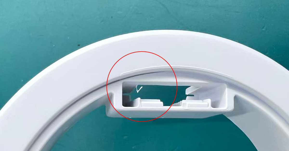
Flash in Injection Molding — Root Causes, Clamp Force, and Process Window Control
A process technician at an electrical components manufacturer is standing in front of a 250-ton injection molding machine running a 4-cavity PC/ABS connector housing mold. The parts are coming out with a thin film of plastic along the parting line — approximately 0.08–0.15 mm thick, extending 3–5 mm from the part edge on each of the four cavities. The flash must be trimmed manually by an operator with a deburring knife, adding an estimated 6 seconds of labor per shot — 4,500 shots per day — translating to 7.5 hours of additional labor per shift, or approximately ¥24,000 per month at local labor rates.
The technician increases clamp force from 200 tons to 240 tons. The flash gets thinner — from 0.15 mm to 0.08 mm — but does not disappear. At 250 tons, the machine’s maximum clamp force, the flash is still present at 0.05–0.06 mm. The customer’s incoming QC specification allows a parting line witness line no thicker than 0.03 mm with no protruding material. At 0.05 mm, every shot is a cosmetic reject.
The root cause is not insufficient clamp force. The root cause is a 0.04 mm parting line mismatch caused by localized mold wear at the cavity edges after approximately 180,000 cycles, compounded by a melt temperature 18°C above the material supplier’s recommended maximum — reducing the PC/ABS viscosity from the specified 240 Pa·s to approximately 160 Pa·s, allowing the low-viscosity melt to penetrate a parting line gap that a properly viscous melt would not enter.
What Flash Is — and What It Tells You
Flash is plastic material that escapes from the mold cavity and solidifies in the parting line, around ejector pins, along slide faces, or at vent channels. It appears as a thin film, feather, or web of material attached to the part at the mold parting surface. Unlike a short shot (not enough material) or sink marks (too much localized shrinkage), flash is material that went where it should not have gone — it left the closed cavity volume and entered a space that should have been sealed.
Flash is a signal. It tells you that at some point during the molding cycle, the cavity pressure at a specific location exceeded the sealing force keeping the mold closed. That sealing force comes from two sources: the clamp force holding the mold halves together, and the mechanical stiffness of the mold steel resisting local deflection. When cavity pressure at any location exceeds the combination of clamp force distribution and local mold stiffness, the mold surfaces separate microscopically — and molten plastic, under injection pressure, flows into the gap.
The gap required to produce flash is surprisingly small. For a low-viscosity material like PA6 at standard processing temperature, a parting line gap of 0.01–0.02 mm is sufficient for flash to form. For higher-viscosity materials like PC or PC/ABS, the threshold is approximately 0.03–0.05 mm. For highly filled materials with paste-like viscosity (30% GF PPS, highly filled PEEK compounds), the gap threshold can be 0.05–0.08 mm — the filled material is too viscous to enter very small gaps.
The Physics: Cavity Pressure vs. Clamp Force
During injection and packing, the plastic pressure inside the cavity acts on every surface of the cavity. The force trying to open the mold is the cavity pressure multiplied by the projected area of the part (plus runner) onto the parting plane. The force keeping the mold closed is the clamp force of the injection molding machine.
The fundamental flash condition is:
Cavity pressure (MPa) × Projected area (cm²) > Effective clamp force (kN) at that location
But this is not a simple yes/no check at the machine level. Clamp force is not distributed uniformly across the mold face. The force is applied by the machine’s toggle or hydraulic clamping mechanism through the platen, and the platen deflects under load — the center of the platen bows outward under clamp force, reducing the effective clamping at the mold center. The tie bars stretch, the mold plates bend, and the local clamping pressure at the cavity edge may be significantly lower than the nominal clamp pressure calculated by dividing the clamp tonnage by the mold base area.
Flash typically appears at the location of peak cavity pressure — which is not necessarily the center of the part. It is the location where the local cavity pressure exceeds the local clamp pressure plus the mold steel’s resistance to deflection. A mold with inadequate support pillars behind the cavity, or with insufficient mold plate thickness, will deflect locally under cavity pressure even when the machine’s total clamp tonnage is theoretically adequate.
Six Root Causes of Flash
Flash has multiple independent causes. The corrective action depends on identifying which cause is dominant — treating flash from a worn parting line by increasing clamp force may temporarily reduce the flash but accelerates the wear that caused it.
Cause 1: Insufficient Clamp Force
This is the first thing every technician checks, and for good reason — it is the most common cause of flash in molds running on machines near the limit of their clamp capacity.
The required clamp force is calculated as:
Required clamp (tons) = Projected area (cm²) × Cavity pressure (bar) × 0.00102
The projected area is the area of the part (plus runner) projected onto the parting plane — not the surface area of the part. For a rectangular part 150 × 100 mm with a 4-cavity mold and a 6 mm diameter runner system, the projected area is approximately:
| Element | Projected Area (cm²) |
|---|---|
| 1 cavity (15 × 10 cm) | 150 |
| 4 cavities | 600 |
| Runner system | ~40 |
| Total | 640 |
The cavity pressure is material-dependent and process-dependent. Typical peak cavity pressures:
| Material | Typical Peak Cavity Pressure (bar) | Notes |
|---|---|---|
| PP, PE (easy flow) | 200–350 | Low viscosity, low pressure |
| ABS, PS | 300–450 | General purpose |
| PC, PC/ABS | 400–550 | Higher viscosity |
| PA6, PA66 (unfilled) | 350–500 | Low viscosity but high mold temp |
| PA6/66 (30% GF) | 500–700 | Higher viscosity requires higher pressure |
| POM | 500–700 | Rapid crystallization demands high packing |
| PBT (30% GF) | 400–600 | |
| PEEK, PPS | 600–900 | High melt viscosity |
For the 4-cavity PC/ABS example with 640 cm² projected area — assuming a peak cavity pressure of 480 bar — the required clamp force is:
640 × 480 × 0.00102 = 313 tons
If the machine is 250 tons, the clamp force is insufficient by approximately 63 tons. The mold should never have been run on this machine — it requires a 350-ton or 400-ton machine at minimum.
The safety factor rule: specify clamp force at 1.2–1.3× the calculated requirement. A 313-ton theoretical requirement means a 380–400 ton machine. The safety factor accounts for process variation, material batch viscosity differences, and the non-uniform distribution of clamp force across the mold face.
Cause 2: Parting Line Damage or Wear
The mold parting line is a precision surface. The two mold halves are ground flat, and the parting surfaces around each cavity are typically spot-faced or ground to a flatness of 0.01–0.02 mm across the sealing area. After 100,000–500,000 cycles, depending on the mold steel, material abrasiveness, and clamping practice, the parting line wears — and the wear is not uniform.
Wear concentrates at specific locations:
- The cavity edge, where the parting line width is narrowest
- Locations where flash from previous cycles has been hammered into the parting surface, creating micro-indentations
- Slide and lifter faces that open and close with every cycle
- Ejector pin bores that have worn clearance
A parting line that was ground to a 0.01 mm flatness when new may develop a localized 0.03–0.05 mm gap at the cavity edge after 200,000 cycles. The gap is invisible to the naked eye under shop lighting, but it is deep enough for PC to penetrate under injection pressure.
Detection: Shut down the mold, clean the parting surfaces, apply a thin layer of Prussian blue (engineer’s blue), close the mold under full clamp force without injecting, open it, and check the contact pattern. Areas where the blue has not transferred indicate a gap in the parting line — those locations will produce flash.
Corrective action: For minor wear (gaps <0.03 mm), spot grinding or hand stoning of the parting surface can restore flatness. For gaps >0.03 mm, the mold must be disassembled and the parting surfaces re-ground. For deep wear at the cavity edge, weld repair followed by re-machining and grinding is required. Typical cost: ¥3,000–8,000 for spot grinding, ¥15,000–40,000 for weld repair and re-machining, depending on mold size and steel type.
Cause 3: Injection Pressure and Speed Outside the Process Window
Every combination of material, mold, and machine has a process window — a range of injection pressures and speeds within which the mold seals and the part fills completely. Outside that window, flash appears.
The upper boundary of the process window is the flash limit — the injection pressure at which the cavity pressure at the weakest point on the parting line exceeds the local clamping force. The flash limit is specific to a mold-machine-material combination. Running the same mold on different machines may shift the flash limit because of differences in platen stiffness and clamp force distribution.
Factors that push the process toward the flash limit:
- Excessive melt temperature. A hotter melt has lower viscosity, penetrates smaller parting line gaps, and requires less pressure to produce flash. The viscosity of PC drops by approximately 35–50% for every 20°C increase in melt temperature above the mid-range. A technician who raises the melt temperature to improve filling of thin ribs is simultaneously lowering the flash threshold.
- Excessive injection speed. Higher injection speed produces higher peak cavity pressure at the end of fill — the sudden deceleration of the melt front creates a pressure spike that can briefly exceed the clamp force even when the steady-state packing pressure is within limits.
- Excessive packing (hold) pressure. Packing pressure acts on the entire cavity volume. A hold pressure of 80 MPa (800 bar) on a 640 cm² projected area requires 522 tons of clamp force — more than many medium-tonnage machines can provide. The hold pressure setting must account for the clamp force available.
- Oversized shot size. An excessive cushion (material remaining in the barrel after injection) or an oversized shot can cause overpacking at the end of fill, creating a pressure spike that produces flash.
Diagnostic test: Conduct a gate-seal study (vary hold time, measure part weight) combined with a clamp force reduction test (reduce clamp force in 5% increments, observe the onset of flash at each clamp setting). The intersection of the two curves identifies the process window boundaries.
Cause 4: Mold Deflection Under Cavity Pressure
A mold is not infinitely stiff. Under cavity pressure, the mold plates bend. The deflection at the cavity center — where the unsupported span is largest — can be 0.02–0.10 mm depending on the mold plate thickness, the support pillar layout, and the cavity pressure. This deflection opens a gap at the parting line, directly at the cavity, where the plastic is.
Mold deflection is the most common cause of flash that resists clamp force increases. If the mold plate is bending under cavity pressure, increasing the clamp force from 200 to 250 tons does not eliminate the bending — it may reduce the gap slightly, but the mold plate continues to deflect because the clamp force is applied to the outside of the mold, not directly behind the cavity.
The mold design solution is support pillars: hardened steel columns positioned directly behind the cavity, connecting the cavity plate to the back plate, providing direct mechanical support at the location of peak cavity pressure. A mold with no support pillars behind the cavity relies on the bending stiffness of the cavity plate alone. A mold with support pillars on 60–80 mm centers transfers the cavity pressure directly to the back plate through the pillars, reducing deflection by 60–80%.
The back plate itself must be adequately thick. A rule of thumb: back plate thickness should be 1.5–2.0× the maximum unsupported span between support pillars or clamp slots, with a minimum of 40 mm for molds up to 400 × 400 mm, and 60–80 mm for larger molds.
Cause 5: Venting Too Deep
Vents are intentional gaps in the parting line — typically 0.01–0.03 mm deep — that allow air to escape from the cavity during filling. If a vent is machined too deep, the vent itself becomes a flash path: the gap is large enough for the melt to enter and solidify, producing a thin fin of material at the vent location.
Vent depth limits by material:
| Material | Maximum Vent Depth (mm) | Notes |
|---|---|---|
| PE, PP | 0.01–0.02 | Lowest viscosity — shallowest vents |
| PA6, PA66 | 0.01–0.015 | Very low viscosity when molten |
| ABS | 0.02–0.03 | |
| PS | 0.02–0.03 | |
| PC | 0.03–0.05 | Higher viscosity, tolerates deeper vents |
| PC/ABS | 0.03–0.04 | |
| POM | 0.02–0.03 | Low viscosity at processing temp |
| PBT | 0.02–0.04 | |
| PEEK, PPS | 0.03–0.05 | Very high viscosity, flash unlikely through vents |
A vent that produces flash is too deep. The corrective action is to reduce the vent depth — typically by re-machining the vent land (the flat section at the cavity edge, before the vent channel drops to a deeper relief) to the correct depth for the material.
Cause 6: Worn Ejector Pin or Slide Clearance
Ejector pins and slides have running clearances — typically 0.01–0.02 mm per side for ejector pins and 0.02–0.04 mm for slides. After extended cycling, the clearance increases due to wear on both the pin/slide and the bore/guide. When the clearance exceeds approximately 0.03 mm for low-viscosity materials or 0.05 mm for higher-viscosity materials, flash can form around the pin or along the slide face.
Ejector pin flash appears as a thin ring of material around the pin head on the part surface. Slide flash appears as a fin along the slide parting line, perpendicular to the main parting line.
Corrective action: Replace worn ejector pins (¥50–200 per pin) and ream or sleeve worn bores. For slides, re-machine the wear surfaces and re-fit the slide to its guide. In severe cases, build up the worn surfaces with weld and re-machine to original dimensions.
The Diagnostic Sequence
When flash appears, the systematic troubleshooting approach is:
| Step | Check | If Yes | If No |
|---|---|---|---|
| 1 | Is the clamp force adequate for the projected area and material? (Calculate, don’t guess) | Go to Step 3 — the machine may be too small for the mold | Go to Step 2 |
| 2 | Does reducing injection speed by 20% or lowering melt temperature by 10°C reduce or eliminate the flash? | Process window issue — optimize parameters (go to Step 4) | Go to Step 3 |
| 3 | Inspect the parting line under magnification (10×). Are there wear marks, pitting, or discoloration at the flash location? | Parting line damage — repair required | Go to Step 4 |
| 4 | Does the flash appear at specific ejector pins or slide faces, but not along the main parting line? | Component clearance issue — replace pins, re-fit slides | Go to Step 5 |
| 5 | Is there a vent at the flash location? Measure the vent depth with a feeler gauge | Vent too deep — re-machine vent land | Mold deflection likely — add support pillars or increase plate thickness |
When Is Flash Acceptable?
Almost never. Unlike sink marks, which have cosmetic class allowances, or weld lines, which can be positioned in low-stress regions, flash is fundamentally a defect — material that should not be present on the part. The only exception is in applications where a witness line at the parting line is permissible and the part is mechanically functional (Class C or industrial), in which case a parting line witness (surface mark, not a protruding fin) may be acceptable.
However, flash is never acceptable when:
- The part is Class A cosmetic (visible, critical surface)
- The flash interferes with assembly (prevents parts from seating, blocks screw bosses)
- The flash creates a sharp edge that is a handling or safety hazard
- The flash location is a sealing surface (gasket groove, O-ring face, mating flange)
- The flash enters a functional clearance (living hinge gap, snap-fit retention feature)
The technician at the electrical components manufacturer eventually identified two independent causes through the diagnostic sequence. First, a mold inspection revealed a 0.04 mm parting line gap at the cavity edges — localized wear after 180,000 cycles from an abrasive PC/ABS grade. The parting surfaces were spot-ground to restore flatness (¥5,000, two days of downtime). Second, the melt temperature was reduced from 288°C to 268°C — within the material supplier’s recommended range of 260–280°C — which increased the melt viscosity by approximately 40% and raised the gap threshold for flash formation from 0.04 mm to approximately 0.06 mm.
After the repair and process adjustment, the mold produced flash-free parts at 200 tons clamp force — well within the 250-ton machine’s capacity. The operator performing manual flash trimming was reassigned to quality inspection, recovering ¥24,000 per month in labor cost. The mold life was projected to deliver another 150,000–200,000 cycles before the next parting line maintenance.
Flash is not a clamp force problem that happens to appear at the parting line. It is a gap problem that the clamp force reveals. Find the gap — whether from insufficient tonnage, mold wear, local deflection, or an over-deep vent — and you find the solution.