Family Mold Design Guide — Balancing Dissimilar Parts in One Tool
A product ships as a set: a connector, a rear cover, and a support bracket — three parts that assemble into one device. The buyer asks for three molds and gets three quotes. The moldmaker comes back with a fourth option: one mold, three cavities, three different parts, one cycle. That is a family mold — and the quote is roughly 40% lower than the three separate tools.
The savings are real, but they are bought with engineering. A family mold asks one runner system to fill three parts with different flow lengths, one cycle time to cool three wall thicknesses, and one mold base to hold three shrinkage rates. Every one of those conflicts has a design solution — and every one has a failure mode when the design skips it. This guide covers the design work that makes a family mold hold production tolerances instead of becoming a permanent sorting station. For the economic decision — when a family mold is the right investment at all — start with the multi-cavity and family molds overview.
The Two Types of Family Molds
Family molds fall into two categories, and the design requirements differ sharply between them.
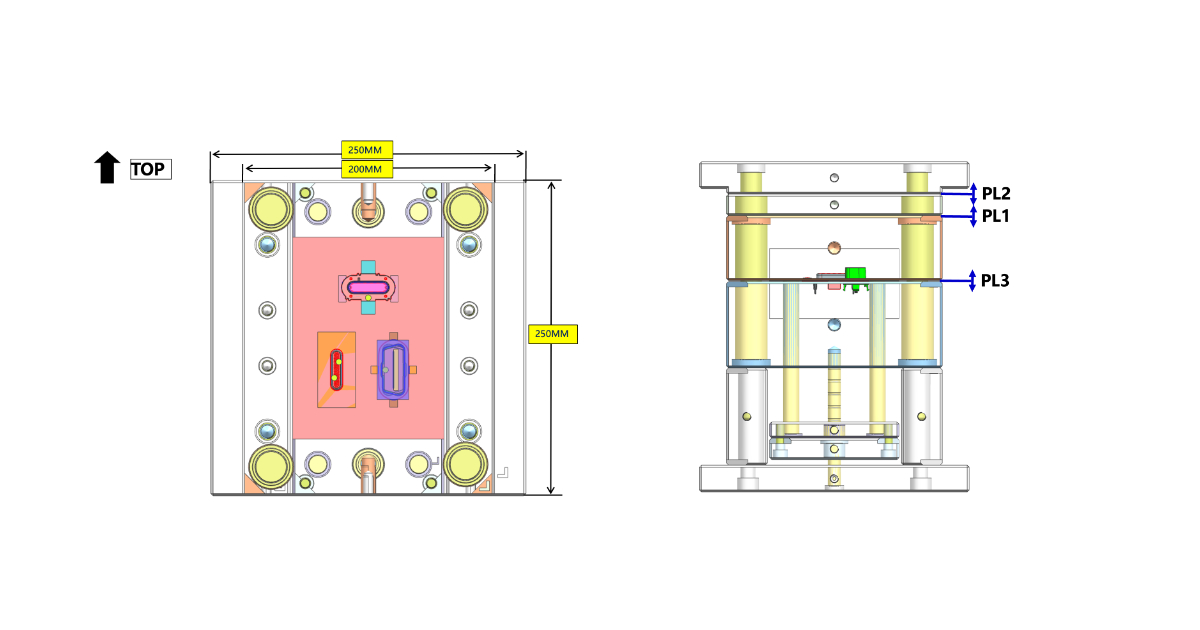
Set molds. All cavities produce parts of one assembly, with matched demand: a left and right housing half, a connector with its cover, a base with its bracket. Every cycle produces one complete set. Set molds are the classic family mold case — our automotive OBD program runs a 1+1+1 configuration producing the connector, rear cover, and support bracket from one tool in one shot.
Mixed molds. The cavities produce unrelated parts that happen to share material, color, and production timing. The demand for each part is independent — and that is the structural problem. When one part’s order volume drops, its cavity still runs with every shot, producing inventory nobody asked for. Mixed molds are almost always a mistake above prototype volumes; matched-demand set molds are the defensible application.
The rest of this guide assumes a set mold. If your parts do not assemble into one product, the design work below does not rescue the economics — split the tool.
Cavity Layout — Clamp Force and Flow Length
The first design decision is where the cavities sit in the mold base, and it is decided by two constraints that pull in opposite directions.
Clamp force balance. The projected area of each cavity, multiplied by cavity pressure, must sum to a resultant force that passes through the mold center. If the large part sits on one side of the mold and the small parts on the other, the clamp force distribution is asymmetric — the platen deflects, the parting line opens unevenly, and the small parts flash while the large part is underpacked. Layout rule: distribute cavities around the sprue so the weighted center of projected areas sits within 5% of the mold center. For a connector (large projected area), a cover (medium), and a bracket (small), the bracket goes opposite the connector, not next to it.
Flow length balance. The runner from the sprue to each cavity should be as equal as possible — but with dissimilar parts, geometric equality is impossible and also not the goal. What matters is that each cavity’s gate delivers melt at the right flow rate for its part volume. The two constraints conflict: clamp balance wants the big cavity centered, flow balance wants short runner paths to the small cavities. The layout that satisfies both is usually a compromise reached in DFM, not an obvious arrangement.
| Design Factor | Set Mold (matched demand) | Mixed Mold (independent demand) |
|---|---|---|
| Primary risk | Fill/cycle mismatch between cavities | Inventory imbalance, idle cavity |
| Layout driver | Clamp force symmetry + flow length | Material/color commonality |
| Economic logic | One tool replaces 2–3 tools | Only if timing and demand coincide |
| Verdict | Defensible below ~30K sets/year | Avoid above prototype volume |
Balancing the Fill — Per-Cavity Gate Sizing
A multi-cavity mold for identical parts balances by making every flow path geometrically identical. A family mold cannot do that — the parts differ in volume and flow length by design. Balancing a family mold is per-cavity gate engineering, and it starts with numbers, not trial shots.
Weight ratio. The shot weight of the largest part divided by the smallest sets the difficulty class. A ratio up to 3:1 is routinely balanceable with gate sizing. Between 3:1 and 5:1, expect a cycle time penalty and plan for valve gating. Above 5:1, the small cavity sits under full injection pressure for the entire fill time of the large part — overpacking, flash, and dimensional drift are near-certain unless the small cavity’s gate can be closed independently. Above 5:1 is the point where a family mold should be rejected in DFM.
Gate land sizing. Each cavity’s gate is sized for its own fill time. The working equation is the orifice flow relationship: flow rate scales with gate area, so the gate cross-section for each cavity is set proportionally to the cavity shot volume divided by its target fill time. In practice: the large part gets the large gate and the fill-time margin; the small part gets a restricted gate that throttles its fill to roughly the same fill time as the large part. A small part that fills in 0.4 seconds while the large part takes 1.2 seconds is the failure signature — the small cavity is done filling and begins packing while the screw is still advancing.
Why MeltFlipper-style balancing does not apply. Shear-induced imbalance correction technologies — the melt rotation geometry developed for geometrically balanced multi-cavity runners — solve a distribution problem between identical cavities. A family mold’s imbalance is a sizing problem between different cavities. Per-cavity gate restriction is the tool that addresses it; runner rotation is not.
Verification in T0. The fill balance is verified with a short-shot series, same as any multi-cavity tool: partial fills at nominal injection speed must show all cavities reaching comparable fill percentages at the same screw position, and 30-shot weight checks should hold cavity-to-cavity variation under 1% of mean part weight. If cavity #2 fills to 95% while cavity #1 sits at 80%, the gate lands are re-cut — this is normal mold development, not a trial failure. See gate design guide for gate types and land dimensions by material.
Packing Strategy — The Valve Gate Decision
Fill balance solves the first half of the problem. The second half is packing: after fill, each part needs its own holding pressure and holding time. The thin-wall cover needs a short, sharp pack; the thick bracket needs a long, gentle pack. A single screw cannot give both at once — the shared runner means every cavity sees the same holding pressure.
Two configurations resolve this:
Cold runner with per-cavity gate restriction. The restricted gate on the small part freezes off early, cutting its cavity off from holding pressure while the large part continues to pack. This works — and it is what the OBD 1+1+1 tool uses, with a cold runner and gate sizing set in DFM — but the freeze-off timing is material- and temperature-dependent. A process change shifts it; the balance is stable only within the validated process window.
Sequential valve gating. Each cavity gets a hot-runner valve gate with independent open/close timing: the large cavity opens first, the small cavities open when the flow front passes their gates or at a timed delay, and each valve closes to end its cavity’s pack phase independently. This is the closest thing to per-cavity process control that a family mold can have — at the cost of a valve-gated hot runner system, which adds roughly $8,000–15,000 to the tool for a 2–4 gate manifold.
| Packing Method | Tool Cost | Control | Best For |
|---|---|---|---|
| Cold runner + restricted gates | Baseline | Freeze-off timing only | ≤ 3:1 weight ratio, stable process |
| Sequential valve gates | + $8K–15K | Independent pack per cavity | > 3:1 ratio, tight tolerances, high volume |
The decision is made in DFM against the weight ratio, the tolerance requirements, and the annual volume — not by defaulting to the cheaper option and hoping the freeze-off lands in the process window.
Zoned Cooling — One Mold, Different Temperatures
The cycle time conflict is the family mold’s most visible inefficiency: the thickest part sets the cycle, and every thinner part waits. What is less visible is that the parts also want different mold temperatures. The 3.5 mm bracket cools best with a mold at 70°C; the 1.5 mm cover would prefer 50°C. One mold temperature is a compromise that degrades both.
Zoned cooling addresses both problems with independent cooling circuits per cavity:
- Separate circuits. Each cavity gets its own cooling circuit with its own flow control valve on the mold manifold, so coolant flow rate — and therefore heat removal — is tuned per cavity, not averaged across the mold.
- Thermal separation. Cavities that require genuinely different mold temperatures need thermal isolation between zones — air gaps or insulation plates machined into the mold base between temperature zones. Without isolation, the zones bleed into each other and the temperature difference collapses.
- Cooling design per part. The channel layout around each cavity follows the part geometry — see the cooling system design guide for channel layout rules. In a family mold, the design is done per cavity, then integrated.
Shrinkage interacts with cooling. Different parts run at different temperatures, shrink at different rates, and shrink by different amounts — even in the same material, a thick wall shrinks more than a thin wall. The mating features between family mold parts (snap fits, locating ribs, screw bosses) must be designed against the as-molded dimensions each part will actually reach, predicted by mold flow simulation — not against nominal CAD values. A snap fit dimensioned from CAD with 0.1 mm interference can arrive at the assembly line with 0.05 mm of clearance because the two parts shrank differently.
The 10-Point Family Mold DFM Checklist
Before steel is cut, every family mold layout should pass these ten checks:
- Matched demand. All parts assemble into one product at the same rate. Mixed-demand cavities are rejected or the mold is split.
- Weight ratio under 5:1. Above 3:1, valve gating is budgeted; above 5:1, the layout is rejected.
- Clamp force symmetry. Weighted projected-area center within 5% of mold center; no side of the mold carries the full load of the largest cavity.
- Per-cavity gate sizing. Each gate land sized for its cavity’s shot volume and target fill time; no cavity shares a gate dimension by convenience.
- Packing method selected. Cold runner with freeze-off gates or sequential valve gating — chosen in DFM against ratio and tolerance, not at T0.
- Zoned cooling. Independent circuits per cavity; thermal isolation where cavities need different mold temperatures.
- Shrinkage-differentiated tolerances. Mating features dimensioned against predicted as-molded dimensions per part, from mold flow data.
- Cavity numbering. Each cavity engraved with an identifier on a non-functional surface for cavity-specific quality tracking.
- Ejector balance. Ejector plate stiffness checked against the combined ejection load of all cavities; per-cavity ejection forces equalized.
- Spare insert strategy. A family mold cannot run a partial cavity set — if one cavity insert is damaged, the whole tool is down. Spare inserts for the highest-wear cavity are specified at tool purchase, and the mold steel selection accounts for the shared mold base serving the full set.
Frequently Asked Questions
What is the maximum weight ratio between parts in a family mold?
Up to 3:1 is routinely balanceable with per-cavity gate sizing. From 3:1 to 5:1, plan for sequential valve gating and accept a cycle time penalty. Above 5:1, the small cavity overpacks while the large cavity fills — reject the layout in DFM.
Do family molds need hot runners?
No. Cold runner family molds with per-cavity gate restriction work well for weight ratios up to about 3:1 — the OBD 1+1+1 tool is a cold runner design. Hot runners become the right choice when valve gating is needed for independent packing, or when the cold runner volume would dominate the shot weight.
How is fill balance verified on a family mold?
Short-shot series at nominal injection speed: at the same screw position, all cavities should show comparable fill progress. Then a 30-shot weight check — cavity-to-cavity variation under 1% of mean part weight. The pass criteria are per-part, not per-shot: each part must meet its own dimensional spec, and the balance check confirms the fill sequence is stable.
What happens when one cavity wears out or is damaged?
The whole tool stops — a family mold has no partial production mode. That is why the spare insert strategy is checklist item 10. The economics of a family mold should include the cost of spare inserts for the highest-wear cavity and the downtime exposure of the full set.
When should a family mold be split into separate tools?
Above roughly 30,000 sets per year, the cycle time penalty and scrap risk outweigh the tooling savings. Also split when demand is not matched, when the weight ratio exceeds 5:1, or when assembly fit tolerances are tighter than the cavity-to-cavity variation the layout can hold. The full decision table is in the multi-cavity and family molds overview.
A family mold is a legitimate engineering solution to a matched-set problem — not a cost-cutting trick. The tooling saving is real, roughly 40% versus separate molds, but it converts upfront cost into design complexity: per-cavity gates, a packing strategy, zoned cooling, and shrinkage-differentiated tolerances. When those four elements are engineered, the tool runs production-quality sets cycle after cycle. When they are skipped, the savings reappear as sorting labor, scrapped sets, and a mold that cannot hold its own tolerances. Our multi-cavity mold manufacturing service builds both balanced multi-cavity tools and matched-set family molds, with the OBD 1+1+1 program as the published reference. Request a DFM review for your part set →