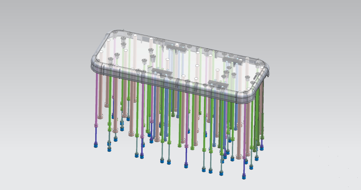
Ejector System Design for Injection Molds — Pins, Blades, Stripper Plates, and Return Sequencing
A mold designer is reviewing T1 samples from a new tool for a medical device housing — a 4-cavity mold producing a PC/ABS enclosure with a 55 mm deep cavity, 2.0 mm walls, and a polished SPI A-2 exterior finish. The parts eject consistently. The cycle time is 24 seconds. The cosmetic quality at the gate area is perfect. There is just one problem: every part shows four circular ejector pin marks on the exterior surface — each approximately 6 mm in diameter, raised 0.05 mm above the surrounding surface, and visible under the customer’s 800-lux inspection standard. The Class A surface specification says “no visible ejector marks on the exterior.”
The mold designer placed the ejector pins on the part’s flat exterior face because the interior surface is occupied by 14 PCB standoffs, two snap towers, and a battery compartment wall — none of which had enough flat area for a 6 mm ejector pin. The flat exterior was the only available surface. The result: a mold that produces dimensionally accurate, fully filled, cosmetically defective parts — and a tooling modification that costs ¥12,000 and delays production by ten days.
Ejector system design is the last thing the mold designer specifies and the first thing the customer sees. Every ejector pin leaves a witness mark. The design task is to make those marks invisible, acceptable, or on a surface the customer never looks at.
What the Ejector System Does
After the part cools and solidifies, it is stuck to the core side of the mold. The part has shrunk onto the core — the same differential shrinkage that causes warpage in production now acts as a retention force holding the part in the mold. The ejector system must overcome this retention force, push the part off the core, and allow it to fall free or be removed by a robot — all without deforming, scratching, or marking the part beyond the cosmetic specification.
The retention force is proportional to:
- The shrinkage of the plastic (higher shrinkage = tighter grip on the core)
- The core surface area in contact with the part
- The coefficient of friction between the plastic and the polished steel core
- The draft angle (lower draft = higher retention; a 0.5° draft produces approximately 3× the retention force of a 2° draft)
For a typical enclosure with a 55 mm deep core, 2° draft, in PC/ABS: retention force ≈ 800–1,200 N per cavity. A 4-cavity mold requires approximately 3,200–4,800 N of ejection force — delivered by the ejector system through the machine’s ejector plate, which typically provides 20–80 kN of force over a 100–150 mm stroke.
The ejection force must be distributed across enough ejector elements that no single element exceeds the compressive strength of the plastic at the ejection temperature. Ejecting a hot PP part (still at 80°C when the mold opens) with a single 4 mm pin is guaranteed to punch through the part — an ejection defect caused not by filling or cooling but by inadequate ejector contact area for the material’s compressive strength at the ejection temperature.
The Five Ejector Types
1. Ejector Pins — The Workhorse
Cylindrical pins that push against the part from the core side. Available in standard diameters from 1.5 mm to 25 mm, in hardened H13 steel (48–52 HRC) with a ground OD tolerance of −0.005 to −0.015 mm for a slip fit in the ejector plate bore.
| Pin Diameter (mm) | Max Ejection Force per Pin (N) — PC/ABS at 90°C | Max Force per Pin (N) — PP at 80°C | Typical Application |
|---|---|---|---|
| 3 | 60–90 | 30–50 | Small features, narrow ribs |
| 4 | 110–160 | 55–85 | Ribs, bosses, medium features |
| 5 | 170–250 | 85–130 | Standard elements on flat surfaces |
| 6 | 250–360 | 125–190 | Standard for enclosures, housings |
| 8 | 450–630 | 220–330 | Large flat surfaces, structural parts |
| 10 | 700–1,000 | 350–520 | Heavy parts, deep draw |
Ejector pins leave a circular witness mark. The mark is a combination of:
- The pin face impression: the polished pin face transfers its surface finish to the part. A polished pin face (Ra 0.4 μm) leaves a glossy mark; a textured pin face can blend into a textured part surface.
- Thermal expansion differential: the pin is at the same temperature as the core steel (50–80°C), while the part surface it contacts is at 80–100°C. The cooler pin face locally chills the part surface, creating a visible halo around the pin mark.
- Mechanical indentation: if the ejection force per pin exceeds the plastic’s compressive yield strength at the ejection temperature, the pin indents the surface rather than pushing against it. The plastic yields locally, and the pin mark is a depression rather than a raised witness.
2. Blade Ejectors — For Ribs and Thin Walls
Rectangular ejector blades with a width-to-thickness ratio of 3:1 to 10:1. Blades eject thin features — ribs, gussets, narrow walls — where a round pin would not fit. The blade thickness is typically 1.0–3.0 mm, and the width is 3–30 mm.
| Blade Thickness (mm) | Blade Width Range (mm) | Max Force per Blade (N) | Typical Application |
|---|---|---|---|
| 1.0 | 3–10 | 40–80 | Thin ribs, gussets |
| 1.5 | 5–15 | 90–160 | Medium ribs, narrow walls |
| 2.0 | 6–20 | 160–280 | Structural ribs, deep walls |
| 3.0 | 9–30 | 350–600 | Thick ribs, heavy sections |
Blades are oriented with the thin dimension parallel to the rib or wall direction. The blade contacts the rib along its length, distributing the ejection force over the rib cross-section rather than at a point. The witness mark is a rectangular impression on the rib surface — acceptable on internal ribs, unacceptable on cosmetic surfaces.
3. Sleeve Ejectors — For Bosses and Cores
A hollow cylindrical sleeve that surrounds a core pin. The sleeve ejects the part while the core pin stays fixed, providing ejection around the entire circumference of a boss or a circular feature. Sleeves are standard for ejecting bosses that are too tall for the surrounding ejector pins to reach, or for bosses where the ejection force must be applied as close as possible to the shrink-fit interface between the plastic and the steel core pin.
| Sleeve ID (mm) | Sleeve OD (mm) | Wall Thickness (mm) | Max Force (N) |
|---|---|---|---|
| 3 | 5–6 | 1.0–1.5 | 60–120 |
| 4 | 6–8 | 1.0–2.0 | 110–220 |
| 6 | 9–12 | 1.5–3.0 | 250–500 |
| 8 | 12–16 | 2.0–4.0 | 450–880 |
| 10 | 15–20 | 2.5–5.0 | 700–1,400 |
The sleeve outer surface contacts the plastic, and the witness mark is an annular ring around the boss. On a boss where the mating fastener head or washer covers the top surface, this ring is hidden after assembly — making the sleeve an ideal ejector for boss-heavy parts where pin marks on flat surfaces would be visible.
4. Stripper Plates — For Zero-Visible-Mark Ejection
A stripper plate is a flat plate that contacts the entire perimeter of the part — typically around the outer edge or along a continuous flange — and pushes the part off the core without any localized pin marks. Stripper plates are the solution for Class A surfaces where no pin witness is acceptable.
| Part Type | Stripper Contact Area | Typical Application |
|---|---|---|
| Transparent lenses, light pipes | Perimeter edge or flange | Zero visible marks on optical surfaces |
| Cosmetic enclosures (Class A) | Internal flange, snap-fit ledge | Marks acceptable on non-visible internal features |
| Thin-wall containers | Rim or lip | Full-perimeter ejection, no distortion |
| Gears and precision parts | Hub face or outer diameter flange | Even ejection, no distortion of tooth profile |
The stripper plate is actuated by the same ejector system that drives the pins — connected to the ejector plate through tie rods or directly mounted to the ejector plate. The plate must be guided on hardened leader pins to prevent cocking (tilting) during ejection, which would bind the plate on the core and produce uneven ejection. Stripper plate travel is limited to the part depth plus 2–5 mm clearance — typically 15–60 mm, shorter than the ejector stroke.
5. Air Ejection — For Thin-Wall and Flexible Parts
Compressed air is introduced between the part and the core through micro-valves or porous steel inserts. The air breaks the vacuum between the part and the core and assists ejection. Air ejection is rarely the primary ejection method — it is almost always used as an assist, in combination with pins or a stripper plate, for parts where the vacuum adhesion between the part and the polished core surface is the dominant retention force.
Air ejection is particularly effective for thin-wall containers and cups (wall thickness <1.5 mm) where the vacuum force can exceed the mechanical retention force, and where mechanical ejectors would distort the still-hot part.
Ejector Placement Rules
Rule 1: Place on Non-Cosmetic Surfaces
The first rule of ejector placement is the same as the first rule of gate placement: put the witness marks where the customer will never see them. Ejectors belong on internal ribs, boss tops (covered by the fastener head), the inside of snap-fit features, the underside of flanges, and any surface defined as non-cosmetic on the part drawing.
A DFM review that identifies the available ejector surfaces should happen before the cooling system is designed — because the cooling channels and ejector pins compete for the same real estate in the core steel. The precision machining required for ejector bores (H7 tolerance, Ra 0.8 μm bore finish) is the same class of work as the gate and cooling channel features that share the core geometry. A core with well-placed cooling channels and no room for ejector pins is as problematic as a core with ejector pins blocking every possible cooling channel location.
Rule 2: Balance the Ejection Force
The ejector elements should be arranged symmetrically around the center of the part so that the net ejection force passes through the part’s center of mass. Asymmetric ejection — pins on one side of the part but not the other — tilts the part during ejection, causing it to bind against the core. The binding increases the ejection force, which increases the tendency to mark, which the mold designer addresses by adding more pins — which, if placed asymmetrically, makes the binding worse.
The center of the ejector force should coincide with the geometric center of the part. For a rectangular part, four ejector pins at the corners provide balanced ejection. For a circular part, three or more pins on a bolt circle provide balanced ejection. For an irregular part, the ejector pattern should be designed around the projected center of area, not the closest available flat surfaces.
Rule 3: Never Place Opposite Thin Walls
An ejector pin placed opposite a 0.8 mm wall will deflect the wall before the part releases from the core. The force required to eject the part from the core is distributed across the ejector contact area — but the reaction force is concentrated at the ejector pin location. A thin wall opposite the ejector pin has insufficient bending stiffness to resist the ejection force, and the part deflects locally rather than releasing from the core.
The wall thickness at the ejector location should be at least 1.0 mm for a 4 mm pin and 1.5 mm for a 6 mm pin. If the wall is thinner, the ejector should be relocated to a thicker section — a rib, a boss, a flange, or a gusset.
Rule 4: Maintain Pin-to-Edge Clearance
Ejector pins should be at least 1.5–2.0 mm from any cavity edge, parting line, or core feature. Closer than 1.5 mm, the pin bore breaks through the steel into the adjacent feature, creating a flash path for the plastic. A pin bore that intersects a cavity edge produces a witness mark with a sharp burr — the plastic flows into the clearance gap between the pin and the bore at the edge intersection.
Rule 5: Respect the Draft
Ejector pins must be perpendicular to the parting plane — they cannot follow the draft angle of a sloped or contoured surface. This means that on a drafted wall (2–3° from vertical), the ejector pin face contacts the part surface at an angle equal to the draft angle. The pin face is not parallel to the part surface. The contact is along a line rather than across a circular area, producing a crescent-shaped witness mark and concentrating the ejection force at a line contact.
For drafted surfaces steeper than 2°, the designer should recess the pin face into a flat-bottomed pocket in the core steel, so the pin face is parallel to the part surface. The pocket is an additional machining operation — a flat-bottomed end mill cut into the drafted core surface — but it converts the line contact back to a full-area contact.
Two-Stage Ejection and Early Return
Why Two-Stage Ejection
A part with deep ribs and a tall core may require two ejection stages: the first stage retracts the core or separates a stripper plate from the core surface, breaking the initial vacuum and shrink-fit grip; the second stage pushes the part fully off the remaining core surface with ejector pins. Single-stage ejection on a deep-core part concentrates the entire ejection force at the initial breakaway — the highest-force moment of the ejection cycle — and risks deforming the part or punching through it.
Two-stage ejection is implemented with a mechanical or hydraulic sequencer in the ejector system: the first stage (typically the stripper plate or large-area ejectors) travels 5–15 mm to break the part free; the second stage (pins or sleeves) then completes the ejection stroke. The sequencing can be achieved with delay pins, hydraulic cylinders, or mechanical latches in the ejector system.
Early Return Mechanism
The ejector plate must return to its home position before the mold closes. If the ejector plate is still forward when the mold closes, the ejector pins will collide with the cavity — damaging the pins, the cavity surface, or both. The standard return is by mechanical springs or the machine’s ejector retract stroke. But in a high-speed molding cycle, waiting for the springs to return the ejector plate adds time to the mold-close sequence.
An early return mechanism (also called a positive return or safety return) uses mechanical links — push-back pins contacting the cavity plate during mold closing — to force the ejector plate back to its home position before the core and cavity meet. It is independent of spring force and machine timing, and it eliminates the risk of an ejector pin left in the forward position colliding with a closing cavity.
For molds with deep-draw parts where the ejector stroke exceeds 60 mm, early return is standard practice. For high-cycle molds (cycle time <15 seconds), the time saved by eliminating the spring-return waiting period can be 0.5–1.0 second per cycle — a 3–7% cycle time reduction.
Ejector Surface Finish and Cosmetics
The ejector pin face leaves a witness mark determined by the pin face finish relative to the surrounding part surface:
| Pin Face Finish | Part Surface Finish | Witness Mark Appearance |
|---|---|---|
| Polished (Ra 0.2–0.4 μm) | Polished (SPI A-1/A-2) | Barely visible — glossy spot on glossy surface |
| Polished (Ra 0.2–0.4 μm) | Matte / VDI texture | Visible — glossy spot on matte surface |
| Textured to match | Textured (VDI 27, SPI C-1) | Nearly invisible — texture masks the pin edge |
| Sandblasted (Ra 1.6–3.2 μm) | Any | Flat, slightly rough spot |
The most cosmetically invisible ejector pin mark is one where the pin face texture matches the surrounding surface. On a textured part, texturing the pin faces to the same specification eliminates the visible halo that distinguishes a polished pin from a textured surface. On a polished part (SPI A-1), a polished pin face (Ra 0.2 μm) produces a mark that is invisible under most inspection conditions — but may remain visible under 800-lux angled light.
The medical device housing mold designer who started with ejector pin marks on the Class A exterior revised the ejection: four Ø6 mm pins were removed from the exterior face and replaced with eight Ø3 mm blade ejectors on the internal ribs, four Ø4 mm sleeve ejectors around the PCB standoff bosses, and two Ø8 mm pins on the internal snap-tower faces. The tooling modification cost ¥12,000 and required re-machining the core insert to add the blade ejector slots and sleeve seats. The revised mold produced parts with no visible ejector marks on the exterior surface. The customer approved the T2 samples on the first submission.
Ejector system design is not an afterthought in the mold design process. It is a negotiation between the part geometry (which determines where ejectors can be placed), the cosmetic specification (which determines where ejectors may be visible), and the material properties at ejection temperature (which determine the force each ejector element can apply without damaging the part). The mold designer who resolves this negotiation before the core steel is cut produces a tool that ejects cleanly, marks no visible surface, and runs at the quoted cycle time.