Cooling System Design for Injection Molds — Channels, Baffles, Bubbler Tubes, and Reynolds Math
A mold maker receives a tooling RFQ for a polypropylene container — 180 mm diameter, 120 mm deep, 2.2 mm wall, with a 95 mm deep core that forms the internal cavity. The core is a single block of P20 steel, 140 mm in diameter. The part has a 25-second target cycle time. The mold maker drills two 10 mm water lines through the core, connects them to the mold temperature controller, and ships the tool.
At T1, the cycle time is 42 seconds. The core surface temperature — measured with a contact thermocouple during a short-shot trial — is 72°C, while the cavity side is at 48°C. The 24°C temperature differential is driving differential cooling: the part skin on the core side stays molten longer, the crystalline structure develops differently between the two surfaces, and the part warps toward the hotter core side after ejection — a molding defect caused not by filling or packing but by non-uniform heat removal. The mold maker tries lowering the water temperature from 25°C to 15°C. The core temperature drops to 65°C. Still 17°C above the cavity side. The cycle time drops 3 seconds. Still 14 seconds above the target.
The problem is not the water temperature. It is that two 10 mm straight lines cannot cool a 140 mm diameter, 95 mm deep solid steel core. The heat must travel from the core surface through 60–70 mm of solid steel before it reaches a cooling channel — and steel conducts heat at 30–50 W/m·K, roughly one-tenth the conductivity of aluminum. By the time the core surface heat reaches the water, the water is already at the return temperature and the heat transfer gradient is near zero at the core center.
Cooling system design is not about drilling holes that water flows through. It is about placing heat-removal surfaces close enough to the cavity steel that the thermal resistance from the plastic to the coolant is low enough to meet the cycle time target without creating a surface temperature gradient that warps the part.
Why Cooling Matters — The Time and Quality Equation
Cooling time accounts for 50–70% of the injection molding cycle. The part cannot be ejected until the entire cross-section — including the last-to-freeze core at the thickest section — has cooled below the material’s heat deflection temperature and developed sufficient modulus to withstand ejection forces without permanent deformation. This is why wall thickness is the dominant cycle time lever — cooling time scales with the square of the wall, independent of how well the cooling system performs.
The cooling time for a given wall thickness is approximated by:
t_cool ≈ (s² / (π² × α)) × ln((8/π²) × ((T_melt − T_mold) / (T_eject − T_mold)))
Where:
s= wall thickness (mm)α= thermal diffusivity of the plastic (mm²/s), typically 0.08–0.12 for amorphous, 0.10–0.15 for semicrystallineT_melt= melt temperature (°C)T_mold= mold surface temperature (°C)T_eject= ejection temperature (°C)
The key insight from the equation: cooling time scales with the square of wall thickness and inversely with the mold surface temperature. Halving the wall thickness reduces cooling time by 75%. Reducing the mold surface temperature by 10°C — achievable by moving the cooling channel 5 mm closer to the cavity — reduces cooling time by approximately 12–18% for a typical PP part.
The cooling system’s job is to maintain the cavity surface at a uniform, specified temperature by removing heat from the steel at the rate that the plastic deposits it — approximately 300–600 kJ per kilogram of plastic processed. For a 200 g shot of PP at a 30-second cycle, the heat removal rate is approximately 2.5–5.0 kW — roughly the output of two domestic space heaters, concentrated into a tool the size of a microwave oven.
The Three Modes of Cooling Channel Design
1. Straight Drilled Channels — The Baseline
The simplest and most common cooling method. Straight holes drilled through the mold plates, connected by external hoses or internal milled pockets to form a circuit. The channels are typically 8–14 mm in diameter, placed 1.5–2.5× the channel diameter from the cavity surface.
| Channel Diameter (mm) | Recommended Distance from Cavity (mm) | Recommended Channel Spacing (mm) | Flow Rate at 3 m/s (L/min) |
|---|---|---|---|
| 8 | 12–20 | 20–30 | 9 |
| 10 | 15–25 | 25–38 | 14 |
| 12 | 18–30 | 30–45 | 20 |
| 14 | 21–35 | 35–53 | 28 |
The distance from the cavity surface is a compromise: closer = better cooling but higher thermal stress in the steel (the temperature gradient between the 200°C cavity surface and the 25°C cooling channel wall creates compressive stress at the cavity surface). A channel too close to the cavity can cause heat-check cracking on the cavity surface after 100,000–200,000 cycles, particularly in aluminum or pre-hardened steels.
Straight channels work well for flat or gently curved cavity surfaces with an aspect ratio (depth to width) below approximately 1:1. For a core deeper than its diameter, straight channels leave the center of the core uncooled — the heat must conduct through the entire core radius before reaching a channel in the wall. This is where the second mode becomes necessary.
2. Baffles and Bubbler Tubes — Cooling the Core
Baffles divide a drilled hole into two flow channels — incoming and outgoing — with a blade or plate that runs most of the length of the hole. Water flows down one side of the baffle and returns up the other. The baffle directs flow to the bottom (the tip of the core) and back, ensuring that the coolant reaches the hottest part of the core — the tip that forms the deepest section of the part.
| Core Diameter (mm) | Recommended Baffle Hole Diameter (mm) | Baffle Blade Thickness (mm) | Max Core Depth (mm) |
|---|---|---|---|
| 20–40 | 10–12 | 1.5–2.0 | 80–120 |
| 40–80 | 12–16 | 2.0–2.5 | 120–200 |
| 80–150 | 16–22 | 2.5–3.0 | 200–350 |
The baffle blade should stop 5–8 mm short of the bottom of the drilled hole to allow the coolant to turn around without creating a dead zone at the tip. The blade must be a positive fit in the hole — a gap larger than 0.2 mm between the blade and the hole wall allows coolant to bypass the blade, reducing flow at the tip.
Bubbler tubes are a variation for cores too narrow for a baffle. A small-diameter tube (4–8 mm) is inserted into a drilled hole. Coolant flows up through the inner tube and returns down through the annular gap between the tube and the hole wall. The bubbler tube delivers coolant to the tip of a narrow core — diameters down to approximately 12 mm — where a baffle blade would be too thin to machine or would choke the flow.
| Core Diameter (mm) | Bubbler Tube OD (mm) | Drilled Hole Diameter (mm) | Flow Rate (L/min) |
|---|---|---|---|
| 12–25 | 4–6 | 8–12 | 2–5 |
| 25–40 | 6–8 | 12–16 | 5–10 |
| 40–60 | 8–10 | 16–20 | 10–18 |
3. Thermal Pins — High-Performance Spot Cooling
A thermal pin is a sealed tube containing a working fluid (typically water or methanol under partial vacuum) that transfers heat by evaporation and condensation — a miniature heat pipe. The base of the pin sits in the cooling channel. The tip extends into the core. Heat from the core boils the fluid at the tip; the vapor travels to the cooled base, condenses, and the liquid returns by capillary action. The effective thermal conductivity of a thermal pin is 100–500× that of a solid copper rod of the same dimensions.
Thermal pins are used where a hot spot — a thin steel section, a deep rib, a boss root — cannot be reached by a drilled channel or a bubbler tube. They are standard in high-cavitation molds where a single hot spot limits the cycle time for the entire tool. A thermal pin costs $80–200 and requires a drilled seat in the core, making it a cost-effective spot solution compared to the alternative of adding an entire cooling circuit.
The Reynolds Number — When Flow Matters
Cooling channel design is fundamentally a heat transfer problem, and heat transfer from the channel wall to the coolant is governed by the flow regime. Laminar flow (Reynolds number Re < 2,300) produces a boundary layer at the channel wall that acts as an insulating film — heat transfer through this layer is poor. Turbulent flow (Re > 4,000) disrupts the boundary layer, increasing the heat transfer coefficient by 3–5× compared to laminar flow.
The Reynolds number for a circular channel:
Re = (ρ × v × D) / μ
Where:
- ρ = coolant density (1,000 kg/m³ for water)
- v = flow velocity (m/s)
- D = channel diameter (m)
- μ = dynamic viscosity (0.001 Pa·s for water at 20°C)
For a 10 mm channel: achieving Re = 4,000 requires a flow velocity of approximately 0.4 m/s — a flow rate of about 2 L/min. This is trivially achievable with a standard mold temperature controller. The problem is not achieving turbulent flow in the main channel — it is achieving it in the baffles, bubbler tubes, and narrow sections where the flow velocity drops and the boundary layer re-establishes.
Practical Reynolds number targets for cooling circuits:
| Circuit Type | Target Re | Rationale |
|---|---|---|
| Main channel (straight, ≥10 mm) | >5,000 | Ensures fully turbulent flow with margin for flow splitting |
| Baffle channel | >4,000 per side | After flow split, each side carries half the total flow |
| Bubbler tube annulus | >3,500 | The annular geometry has a higher surface-to-volume ratio; transition to turbulence occurs at a lower Re |
| Conformal channel (printed) | >3,000 | Rough surface finish in printed channels promotes earlier turbulence |
Below these targets, the cooling circuit is removing less heat than the channel geometry would suggest — and the cycle time pays for it.
Pressure Drop — The Practical Constraint
A mold cooling circuit is a closed hydraulic system. The pump in the mold temperature controller delivers a specified flow rate at a specified pressure — typically 3–6 bar (0.3–0.6 MPa) at the supply manifold. Every bend, tee, diameter change, baffle, and bubbler introduces a pressure drop. The total pressure drop across the circuit must not exceed the pump’s delivery pressure at the target flow rate.
| Feature | Approximate Pressure Drop | Notes |
|---|---|---|
| 1 m straight 10 mm channel | 0.02–0.05 bar | At 10 L/min, smooth bore |
| 90° elbow (sharp) | 0.05–0.10 bar | 10 mm, equivalent length ~0.5 m |
| Baffle (two 180° turns) | 0.15–0.30 bar | 12 mm hole at 10 L/min |
| Bubbler tube (annular return) | 0.20–0.50 bar | 6 mm tube in 12 mm hole |
| Flow meter (turbine type) | 0.05–0.15 bar | Varies by model |
| Quick-connect coupling | 0.03–0.08 bar per pair | At 10 L/min |
For a typical circuit with 2 m of straight channel, four elbows, two baffles, and two quick-connect couplings: total pressure drop ≈ 0.1 + 0.3 + 0.4 + 0.1 = 0.9 bar. Well within a 3-bar pump. But add four more baffles and eight more elbows for a complex core with multiple inserts, and the pressure drop can reach 3–4 bar — exceeding the pump capacity and starving the farthest baffles of flow.
The pressure drop constraint means that cooling circuits must be designed as parallel circuits, not series circuits, for multi-cavity or multi-insert tools. Each circuit should serve a limited number of cooling features (2–4 per circuit for baffles; 4–8 per circuit for straight channels) and be independently supplied from a distribution manifold. The parallel flow approach ensures that each cavity sees the same coolant temperature and flow rate.
Cooling Layout Rules
Rule 1: Cool the Core Aggressively
The core side of the mold always runs hotter than the cavity side because the core is surrounded by the plastic part — it has less exposed surface area to radiate heat to the ambient air and the press platens. The core typically requires 30–50% more cooling capacity (more channels, larger diameters, or higher flow rates) than the cavity side for the same temperature setpoint. If the cavity has four 10 mm channels, the core should have six 10 mm channels or four 12 mm channels.
Rule 2: Distance from Cavity — The 2D Rule
The distance from the center of the cooling channel to the cavity surface should be 1.5–2.5× the channel diameter. Closer than 1.5D: thermal stress in the steel, risk of heat-check cracking, and visible channel witness marks on the part surface (particularly on polished or textured surfaces). Farther than 2.5D: the thermal resistance through the steel is too high, and the cooling time increases. The spacing between adjacent channels should be 2.5–4.0× the channel diameter — channels closer than 2.5D apart provide diminishing returns because they are removing heat from overlapping zones of steel.
Rule 3: Turbulent Flow Everywhere
Every segment of the cooling circuit must achieve Re > 4,000 at the design flow rate. This includes the regions downstream of flow splits and the annular returns in bubbler tubes. A circuit that is turbulent in the main channel but laminar in the bubbler return is delivering approximately 20–30% of its theoretical cooling capacity at the hottest point in the tool.
Rule 4: Counter-Flow Configuration
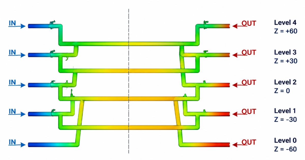
In a two-plate mold, the core cooling circuit should flow in the opposite direction to the cavity cooling circuit — a counter-flow arrangement. This averages the temperature gradient across the part: the hot end of the cavity circuit (where the coolant has picked up heat) is opposite the cold end of the core circuit (where the coolant has just entered), and vice versa. Co-flow (both circuits flowing in the same direction) creates a temperature gradient from the inlet side to the outlet side of the mold, producing differential cooling across the part and consequent warpage.
Rule 5: Circuit Isolation
The cavity side and core side must have independent temperature control circuits with their own temperature controllers. The cavity and core have different thermal masses, different steel volumes, and different cooling requirements. A single controller supplying both sides forces the core and cavity to the same setpoint — but the core will run hotter because it has less cooling capacity relative to the heat it receives. Independent control allows the core to run at 5–10°C hotter than the cavity (standard for semicrystalline materials that benefit from slower cooling on the core side for crystallinity development) or the same temperature (standard for amorphous materials where uniform cooling is the primary goal). This differential temperature control is part of the scientific molding approach — the cooling system is not just removing heat; it is controlling the rate and uniformity of heat removal to achieve a specific part quality outcome.
When to Use Conformal Cooling
Conformal cooling — channels that follow the cavity contour, produced by 3D printing (SLM/DMLS) of the mold insert — is the solution when straight drilled channels cannot follow the cavity geometry. The conformal cooling approach reduces cooling time by 20–40% for parts with deep cores, complex contours, or thick-to-thin transitions that create hot spots inaccessible to straight channels.
Conformal cooling is not a replacement for a well-designed conventional cooling system. It is an escalation for geometries that a conventional system cannot adequately cool. The decision sequence:
- Can straight channels with baffles and bubblers meet the cycle time target? If yes, use conventional cooling.
- Can a thermal pin address the remaining hot spot? If yes, add thermal pins to the conventional design.
- Is the remaining cycle time gap worth the conformal cooling insert cost ($3,000–8,000 per insert)? If yes, use conformal cooling for the specific insert that limits the cycle.
A mold designer who follows these rules for the polypropylene container with the 95 mm deep core would specify: a 20 mm diameter baffled channel running to within 8 mm of the core tip, with a 2.5 mm thick stainless steel baffle blade, four 10 mm straight channels in the core wall at 18 mm from the cavity surface and 30 mm spacing, and independent temperature control for the core (set to 55°C) and cavity (set to 45°C). Total coolant flow rate: 18 L/min at 4 bar, split across two parallel circuits. Reynolds number in the baffle channel: approximately 5,200 at the design flow rate. Target cycle time: 26 seconds — within 1 second of the RFQ target.
Cooling system design is not a plumbing exercise. It is a heat transfer problem disguised as drilled holes. The cycle time that the sales engineer quotes depends on the cooling channels that the mold designer specifies — and the difference between two 10 mm holes and a properly designed baffle-and-channel circuit is the difference between a tool that meets the quoted cycle time and a tool that costs 40% more per part for the rest of its production life.