Burn Marks and Gas Traps in Injection Molding — Venting Design, Diesel Effect, and Process Solutions
A process engineer at an automotive lighting supplier is inspecting a polycarbonate lens — 180 mm long, 4.2 mm thick at the center tapering to 2.0 mm at the edges, gated from a single submarine gate on the underside, with a 15 mm diameter boss at each of four mounting corners. Every 20th to 30th shot produces a lens with a brown-black discoloration — approximately 3–5 mm in diameter — at the boss farthest from the gate. The discoloration is not on the surface; it is embedded in the polymer, visible through the transparent PC as a dark swirl. The customer specification for an automotive forward-lighting lens is zero burn marks — any visible discoloration is a reject. At a rejection rate of 3–4%, the mold is losing approximately 180 acceptable parts per shift. The annualized cost of the rejects at ¥85 per part is approximately ¥1.3 million.
The engineer has tried reducing the melt temperature from 300°C to 285°C — the burn frequency dropped from 5% to 3% but did not disappear. Reducing the injection speed from 85 mm/s to 60 mm/s dropped the frequency further to 2%, but the filling pressure increased from 120 MPa to 155 MPa, approaching the machine’s 175 MPa limit, and the cycle time increased by 1.8 seconds. The burn marks are still present at 2% — one reject every 50 shots.
The root cause is a gas trap at the last-filled boss — the four corner bosses fill last, and the converging melt fronts trap air in the boss cavity with no escape path. The trapped air is compressed to approximately 15–25 bar during the final milliseconds of filling, heating adiabatically to an estimated 350–500°C — above the PC degradation temperature of approximately 340°C. The polymer at the gas-compression boundary thermally degrades, producing the brown-black discoloration. The vent that should be at the boss end face was omitted because the mold designer considered the boss a “blind pocket” that would fill without trapping air — a miscalculation that a mold flow analysis would have caught before the first shot.
What a Burn Mark Is — and the Gas That Causes It
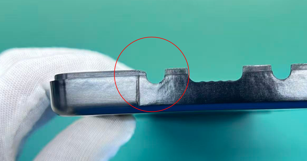
A burn mark is a localized discoloration — typically brown, black, or silver-brown — on or just beneath the surface of a molded part. It forms when trapped gas (air, volatiles, or decomposition products) is compressed to a high pressure and temperature in the final stage of cavity filling, causing thermal degradation of the polymer at the gas-compression interface.
A burn mark is not:
- A splay mark from moisture or shear degradation (though both involve gas)
- A hot spot from a localized hot runner temperature excursion
- Contamination from degraded material sitting in a dead spot in the barrel
Burn marks are always accompanied by trapped gas. Find the gas trap, and you find the burn mark. Fix the gas trap — by venting it, moving it, or filling it more slowly — and you eliminate the burn mark.
The trapped gas can come from four sources:
| Gas Source | Typical Volume | Diagnostic Sign |
|---|---|---|
| Air trapped in the cavity | 1–5 cm³ per shot | Burn at the last-filled region; location predicts consistently by mold flow |
| Volatiles from the melt (residual moisture, low-MW fractions) | 0.1–2 cm³ per shot | Burn distributed across the part or concentrated at the flow front; reduced by material drying |
| Decomposition gases from barrel residence (overheated material, dead spots) | Variable | Intermittent burns; correlated with cycle interruptions or color-change residues |
| Vent obstruction (grease, mold release buildup, debris) | Progressive increase | Burns appear after 500–1,000 cycles, worsen with time, clear after mold cleaning |
The most common source — and the one that mold design can address — is air trapped in the cavity during filling. A cavity is a sealed volume with a single entrance (the gate) and no exit. The air that occupies the cavity before injection must escape somewhere. If it has no escape path, it is compressed by the incoming melt and constitutes approximately 0.1–0.5% of the final part volume — seemingly trivial, but enough to produce a visible burn mark.
The Diesel Effect: Adiabatic Compression of Trapped Gas
The physics that turns trapped air into a burn mark is adiabatic compression — the same principle that ignites fuel in a diesel engine. When a gas is compressed rapidly, its temperature rises. If the compression is fast enough that heat does not have time to conduct away to the surrounding metal and plastic (i.e., the compression is adiabatic), the temperature increase is given by:
T₂ = T₁ × (P₂ / P₁)^((γ−1)/γ)
Where:
- T₁ = initial gas temperature (~503 K / 230°C — cavity wall temperature for PC)
- P₁ = initial gas pressure (1 bar, atmospheric at the start of fill)
- P₂ = final gas pressure (the cavity pressure at the end of fill, typically 300–700 bar)
- γ = ratio of specific heats for air (1.4)
For PC molded at a cavity pressure of 500 bar with a cavity wall temperature of 90°C (363 K):
T₂ = 363 × (500/1)^((1.4−1)/1.4) = 363 × 500^0.286 ≈ 363 × 5.93 ≈ 2,153 K (1,880°C)
The calculated adiabatic temperature of 1,880°C far exceeds the degradation temperature of polycarbonate (~340°C), ABS (~270°C), and most common thermoplastics. In practice, the actual gas temperature is lower — the compression is not perfectly adiabatic because some heat is lost to the mold walls and the melt — but a trapped gas bubble can easily reach 350–600°C, which is sufficient to degrade any common injection molding polymer.
The degraded polymer at the gas-compression boundary is mechanically weak. It has undergone chain scission (for amorphous materials like PC and ABS) or oxidative degradation (for polyolefins). The discolored material is not just a cosmetic defect — it is a localized weak zone with reduced molecular weight, reduced impact strength, and in extreme cases, carbonized material that can flake off the part surface and contaminate downstream assembly.
Five Root Causes and Their Remedies
Cause 1: Inadequate or Absent Venting at the Gas Trap Location
This is the primary cause of burn marks in new molds. The mold flow analysis predicts where the last region of the cavity fills — the “last-filled area” — which is always a gas trap if not vented. The vent must be located exactly at this last-filled point. A vent 5 mm away from the gas trap is a vent that does not function — the gas is trapped 5 mm from the escape path, and the melt reaches the vent before the gas does, sealing it.
Vent placement rules:
- The vent must be at the exact gas trap location predicted by fill simulation — not adjacent, not nearby
- Secondary vents should be placed along the flow path at locations where the melt front slows or converges, such as at weld line meeting planes
- For blind pockets (bosses, deep ribs, corners), the vent goes at the end face — the deepest point of the pocket, opposite the entrance
- Ejector pins can double as vents: a flat-ground ejector pin in the gas trap area with 0.01–0.02 mm peripheral clearance provides a natural vent path to the ejector plate
Vent dimensions by material:
| Material | Vent Land Depth (mm) | Vent Land Width (mm) | Relief Channel Depth (mm) |
|---|---|---|---|
| PE, PP | 0.01–0.015 | 3–6 | 0.5–1.0 |
| PA6, PA66 (unfilled) | 0.01–0.015 | 3–6 | 0.5–1.0 |
| ABS | 0.02–0.025 | 4–8 | 0.5–1.0 |
| PS | 0.02–0.03 | 4–8 | 0.5–1.0 |
| PC | 0.03–0.05 | 4–8 | 0.5–1.0 |
| PC/ABS | 0.03–0.04 | 4–8 | 0.5–1.0 |
| POM | 0.02–0.03 | 4–8 | 0.5–1.0 |
| PBT | 0.02–0.03 | 4–8 | 0.5–1.0 |
| PEEK, PPS | 0.03–0.05 | 4–8 | 0.5–1.0 |
| TPE, TPU | 0.01–0.02 | 3–6 | 0.5–1.0 |
The vent land is the shallow section at the cavity edge — its depth determines whether gas passes through (yes) and plastic passes through (no, if correctly sized). The land width (3–8 mm) provides a short, controlled restriction. Beyond the land, the vent channel drops to a much deeper relief (0.5–1.0 mm) that provides zero restriction to gas flow, channeling the escaping air to the mold exterior.
The land depth rule: 0.01 mm below the material’s flash threshold. If the material produces flash at a parting line gap of 0.03 mm, the vent land depth should be 0.02 mm — deep enough to pass gas, shallow enough to prevent the melt from entering. This is why low-viscosity materials (PE, PP, PA6) require the shallowest vents — their flash threshold is lower.
Number of vents: There is no fixed number. Each gas trap location — each region where the fill simulation shows converging flow fronts or a blind pocket — requires its own vent. A mold with one gate, two core pins, and four bosses may have 5–8 gas trap locations, each requiring a dedicated vent.
Cause 2: Injection Speed Too High for the Available Venting
Injection speed directly controls how fast the air in the cavity is compressed. A higher injection speed gives the trapped air less time to escape through the vents before the melt seals the escape path — and simultaneously produces a faster compression rate, increasing the peak gas temperature.
The relationship between injection speed and burn mark formation is nonlinear. There is a threshold injection speed below which the existing vents can evacuate the cavity air before the melt arrives, and above which the gas is trapped and compressed. This threshold depends on:
- The vent area (total of all vent cross-sections)
- The cavity volume (more air to evacuate = lower threshold speed)
- The fill time (shorter fill time = faster compression = higher temperature)
Diagnostic test: Run a series of shots at incrementally decreasing injection speeds — start at the normal production speed, reduce by 10 mm/s per step, hold all other parameters constant. Record the presence or absence of burn marks at each speed. Plot burn frequency against injection speed. The threshold is the speed at which burn frequency drops to zero. If the threshold speed is below the speed required to fill the cavity completely (i.e., the melt freezes before filling), the venting is inadequate, and mold modification is required.
Profiled injection: Rather than running a single low speed for the entire shot, use a profiled injection: fast fill (80–100 mm/s) for the first 90–95% of the cavity volume, then a sharp deceleration to 20–30 mm/s for the last 5–10% — the region where gas is being compressed. The fast fill for the bulk of the volume prevents premature freezing; the slow fill for the final compression gives the trapped gas time to escape through the vents. This is the standard approach for venting-limited molds where mold modification is not immediately possible.
Cause 3: Gate Location Creating an Unventable Gas Trap
The gate location determines the fill pattern, and the fill pattern determines where the gas traps form. A gate that fills a boss from the open end (the gate is at the boss base, flow goes up the boss wall, meeting at the closed end) creates a gas trap at the blind end of the boss — which is accessible for venting because it faces the parting line or an ejector pin.
A gate that fills the area around the boss first, then fills the boss from the outside-in, creates a gas trap at the base of the boss — which is inaccessible for venting because it is inside the cavity, surrounded by filled plastic. The gas is trapped in the boss, and there is no path to vent it.
The gate location rule for gas trap prevention: the gate should be positioned so that gas traps form at accessible locations — parting line surfaces, ejector pin faces, slide faces, or the end of ribs that reach the parting line. Gas traps at internal cavity features (boss interiors filled from the outside, deep pockets with no parting line access) are venting nightmares.
Cause 4: Material Moisture and Volatile Content
Inadequately dried material introduces water vapor and low-molecular-weight volatiles into the melt stream. These volatiles vaporize at melt temperature and contribute additional gas volume to the cavity — gas that was not accounted for in the venting design. A cavity vented for 3 cm³ of trapped air may be inadequate for 3 cm³ of air plus 1 cm³ of water vapor from undried material.
Material drying requirements:
| Material | Drying Temperature (°C) | Drying Time (hours) | Target Moisture Content |
|---|---|---|---|
| ABS | 80–85 | 2–4 | <0.05% |
| PC | 120 | 3–4 | <0.02% |
| PC/ABS | 90–100 | 3–4 | <0.04% |
| PA6, PA66 | 80–85 | 4–6 | <0.10% (unfilled), <0.05% (filled) |
| POM | 80–90 | 2–4 | <0.05% |
| PBT | 120–140 | 3–5 | <0.02% |
| PEEK | 150 | 4–6 | <0.02% |
A material dryer that is not delivering its rated dew point (typically −30°C to −40°C for engineering resins) produces material at 0.05–0.10% moisture content — 2–5× the target — adding substantial gas volume to the cavity. The diagnostic test is a moisture analyzer measurement of the material at the feed throat. If the moisture content is above specification, the dryer — not the venting — is the root cause of the burn marks.
Cause 5: Dead Spots and Material Degradation in the Barrel
Polymer that sits in a dead spot — a corner of the barrel, behind the check ring, in a hot runner manifold dead leg — for multiple cycles undergoes progressive thermal degradation. The degraded material is darker, more viscous, and carries decomposition gases. When it eventually dislodges and enters the cavity with the next shot, it produces an intermittent burn mark — appearing once every 10–50 shots, never in the same location.
Dead-spot burns are diagnosed by their intermittency and randomness. A venting-related burn is highly consistent — same location, same shape, same frequency (every shot or every other shot). A dead-spot burn is inconsistent — different locations, different severity, appearing in clusters then disappearing for 20 shots.
Corrective action: Purge the barrel with a commercial purging compound (not the production material — degraded material stuck in dead spots will not be dislodged by the same material that created it). Inspect the check ring for wear — a worn check ring creates a recirculation zone where material can stagnate. In hot runner systems, inspect manifold dead legs — any channel with no flow path (a plugged gate, an unused drop location) is a dead spot that accumulates degraded material.
Vacuum Venting — When Conventional Venting Is Not Enough
For parts where venting through conventional parting line and ejector pin clearances is insufficient — typically deep-draw parts, parts with large projected area and short fill times, or transparent parts with zero-tolerance for cosmetic defects — vacuum-assisted venting is the solution.
A vacuum venting system connects the vent channels to a vacuum pump that actively evacuates air from the cavity before and during injection. The cavity is sealed (all vents are connected to the vacuum circuit), a vacuum of 500–700 mbar below atmospheric is pulled, and the injection is triggered when the vacuum setpoint is reached. The reduced initial pressure lowers the peak compression temperature:
For an initial pressure of 0.3 bar (70% vacuum) instead of 1.0 bar, the compression ratio at 500 bar becomes 500/0.3 ≈ 1,667 (vs. 500/1.0 = 500), but the absolute temperature rise is only 60% of the atmospheric case because of the lower starting density — fewer gas molecules are present to be compressed.
In practice, vacuum venting reduces the peak trapped-gas temperature by 40–60%, which can be sufficient to keep the gas temperature below the polymer’s degradation threshold.
Vacuum venting adds approximately ¥15,000–30,000 to the mold cost (vacuum pump, manifold, seals, control system) and 1–3 seconds to the cycle time (vacuum draw-down). It is reserved for applications where the cost of burn mark rejects exceeds the amortized cost of the vacuum system — typically automotive lighting, medical transparent components, and optical parts.
Mold Flow Analysis for Gas Trap Prediction
Mold flow simulation predicts gas trap locations with high accuracy. The fill simulation tracks the advancing melt front, and any region of the cavity where the melt front converges from multiple directions — an “island” of unfilled cavity surrounded by filled cavity — is flagged as a gas trap.
The simulation requires the venting to be modeled: if no vents are specified in the simulation, the gas traps are predicted assuming zero venting (all gas is trapped). If vents are specified at specific locations with specific dimensions, the simulation calculates how much gas escapes through each vent and whether the remaining trapped gas is sufficient to produce a burn.
The standard pre-production workflow:
- Run fill simulation with zero vents → identify all gas trap locations
- Add vents at each gas trap location → re-run simulation with vented boundary conditions
- Verify that no unvented gas traps remain
- If unvented gas traps persist (inaccessible locations), adjust the gate location to shift the fill pattern, or add ejector-pin vents at the gas trap locations
A DFM review that includes gas trap analysis identifies burn mark risks before steel is cut. The cost of adding a vent during mold design is the cost of a machined groove — approximately ¥200–500 per vent. The cost of adding the same vent by modifying a finished mold — disassembly, re-machining, re-assembly, re-qualification — is ¥3,000–8,000 per vent plus 2–5 days of downtime.
The automotive lighting engineer who started with 3–4% burn mark rejects at the PC lens eventually identified two root causes through systematic diagnosis. First, a mold flow analysis of the existing fill pattern confirmed four gas traps at the four corner bosses — each boss was filling from the outside-in, trapping air at the boss end face with no vent path. Second, the material dryer was found to be delivering a −22°C dew point instead of the specified −40°C — worn desiccant — producing PC at 0.04% moisture instead of the target <0.02%, adding water vapor to the trapped air and increasing the gas volume at each boss by an estimated 30%.
The corrective actions: ejector pin vents were added at the end face of each boss (the existing ejector pins were flat-ground to provide a 0.03 mm peripheral vent path to the ejector plate — a ¥2,000 modification per pin that required no mold disassembly beyond removing the ejector pins for grinding). The dryer desiccant was replaced (¥3,000), restoring the −40°C dew point and bringing the material moisture to 0.015%.
After both corrections, the burn frequency dropped from 3–4% to zero — no burn marks in a 5,000-shot validation run. The ¥1.3 million annual reject cost was eliminated. The injection speed was restored to 85 mm/s, the melt temperature to 300°C, and the cycle time to its original value.
Burn marks are a gas problem. If the gas cannot escape, it burns the plastic. The solution is always the same in principle — give the gas a path out — but the art is knowing where the gas is trapped, and whether the vent can be added at that location without mold modification. The mold flow analysis makes the first question answerable; the mold design makes the second question actionable.