Custom Plastic Structural Parts Manufacturer
Precision injection molded structural components for mechanical, electronic, automotive, industrial, medical, and consumer products — from mold design and tooling to mass production.
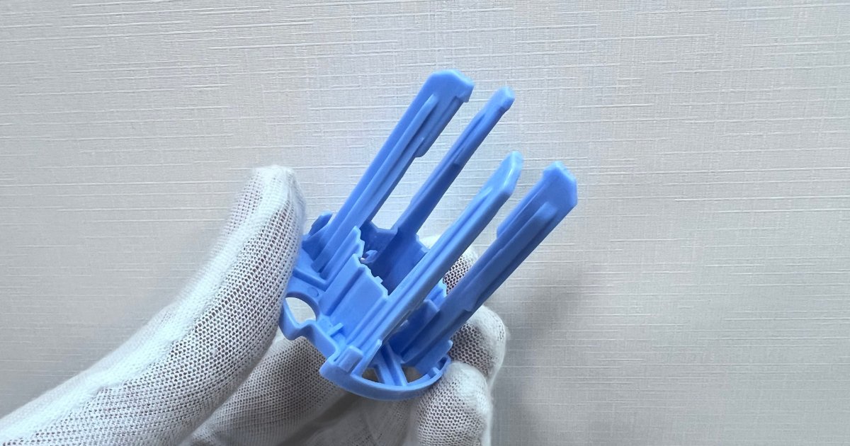
What Are Plastic Structural Parts?
Plastic structural parts are functional components designed to support, position, connect, reinforce, or carry loads within a product or assembly. Unlike cosmetic housings and covers, structural components are primarily engineered around mechanical performance, dimensional stability, assembly requirements, and long-term reliability.
JBRplas molds structural components for OEM programs where the part has to do a mechanical job — carry a load, hold a position through the product’s life, or transfer force through an assembly. These parts are specified by critical dimensions rather than appearance, and the tooling, material, and process plan follow the mechanical requirement.
| Structural Function | Typical Features |
|---|---|
| Support | Ribs, walls, mounting points |
| Positioning | Locating pins, holes, bosses |
| Connection | Clips, tabs, screw bosses |
| Reinforcement | Ribs, gussets, frames |
| Load Transfer | Reinforced sections, thickened areas |
| Assembly | Snap-fits, inserts, fasteners |
| Mechanical Movement | Pivots, guides, bearing locations |
Types of Custom Plastic Structural Parts
Eight structural component families we tool and mold. Each is quoted from the drawing and the mechanical requirement — not from a catalog.
Structural Frames
Internal frames and skeletons that hold a product's layout in place — molded as one part with mounting points, cable routing, and stiffening geometry integrated.
Support Components
Parts that carry and hold internal assemblies — PCBs, modules, batteries, and mechanisms — positioned inside the finished product.
Reinforcement Components
Parts that add stiffness to a product structure — stiffening ribs, gussets, and edge reinforcement molded into the assembly.
Mounting Components
Mounting bases and plates that anchor a product or module — controlled hole patterns, flatness, and fastening features in one molded part.
Internal Mechanical Components
Working parts inside an assembly — levers, guides, cams, and linkage components engineered around load, wear, and clearance.
Positioning Components
Locating and guiding parts — locating pins, alignment blocks, and datum features that fix the position of other components.
Structural Brackets
Load-bearing brackets — a structural family with its own design rules, covered in depth on our plastic brackets page.
Custom Functional Components
Structural parts that don't fit a standard category — evaluated from the drawing and the function the part has to perform.
Plastic Structural Components by Function
The same part family, grouped by the job it performs in the assembly — the way structural parts are actually specified.
Carrying Load
Parts whose primary job is to carry mechanical load — evaluated along the load path, with stress distribution and safety factor reviewed against the service condition.
Supporting Assemblies
Parts that hold other components in position — PCB supports, module carriers, and internal shelves that keep an assembly located through the product's life.
Locating Components
Parts that fix the position of other components — locating pins, alignment features, and datum surfaces that make assembly repeatable part after part.
Fastening & Assembly
Parts that hold an assembly together — screw bosses, clips, snap-fits, and mounting points molded in the same tool as the structure itself.
Adding Rigidity
Parts and features that raise stiffness — ribs, gussets, and frames that add rigidity without adding wall thickness and the weight that comes with it.
Enabling Movement
Parts with a mechanical role in motion — pivots, guides, sliding surfaces, and bearing locations engineered around wear and clearance.
Plastic Structural Part Design Considerations
Structural parts are specified by what they carry and how they locate, not by appearance. Load, geometry, material, and molding behavior have to be evaluated together.
Load & Strength
The design starts from the expected load: static, dynamic, impact, or fatigue. Stress concentration, safety factor, and the service condition are reviewed before wall thickness — and no strength number is promised before the geometry backs it.
Ribs & Gussets
Ribs add stiffness without adding wall thickness — the core lever on a structural part. Height, spacing, and thickness ratios are set against the base wall so the ribs don't print sink marks on the opposite face.
Bosses & Mounting Features
Screw bosses, threaded inserts, mounting holes, and locating bosses are designed as one system with the fastening distances the assembly needs. Boss diameter is sized against the adjacent wall, not added on top of it.
Wall Thickness
Adding thickness is not the way to add strength — thick sections cool unevenly, sink, and warp. Structural parts are designed around uniform walls and smooth transitions, with stiffness coming from geometry instead.
Tolerances & Dimensional Stability
Mating dimensions, mounting holes, locating features, and assembly clearances are toleranced feature by feature against the mating part — then held in production with process capability, not inspection alone.
Warpage & Shrinkage
Long parts, large thin areas, ribbed sections, and asymmetric geometry are the hardest warpage cases. Mold design, gate location, cooling balance, material selection, and part geometry all influence dimensional stability — analyzed before the tool is cut.
Snap-Fits & Assembly Features
Snap hooks, clips, retaining features, and assembly guides let a structural part assemble without fasteners — or stay aligned until screws go in. Cantilever geometry and strain limits are designed so the joint assembles without cracking.
Metal Inserts
Where a structural joint needs metal — threaded inserts, bushings, and shafts are insert-molded in the tool or installed in a controlled secondary step, depending on the feature and the volume.
Materials for Plastic Structural Components
Structural material selection follows the load, not the datasheet alone — stiffness, impact, wear, temperature, and chemical exposure all decide which grade fits.
| Material | Typical Structural Use |
|---|---|
| PA / Nylon | Strength and wear resistance — general structural parts |
| PA-GF | Higher stiffness and dimensional stability — load-bearing parts |
| POM | Low friction and wear — moving components |
| PC | Impact resistance — parts that see knocks or drops |
| PC/ABS | Strength with surface quality — visible structural parts |
| PBT / PBT-GF | Electrical and dimensional applications — parts near electronics |
| PP | Lightweight structural components — chemical exposure |
| PEEK | High-performance applications — temperature and chemical resistance |
Material selection depends on load, temperature, chemical exposure, dimensional requirements, electrical requirements, wear, and production volume.
Plastic Structural Part Manufacturing Capabilities
Depending on part geometry, tolerance, and volume, we select the tooling and molding approach that fits the structural requirement.
Injection Molding
Production molding on 27 machines from 90T to 650T — standard tooling for structural parts at volume.
Multi-Cavity Molds
4, 8, and 16-cavity tools for structural parts in long programs — balanced filling so parts from every cavity assemble the same.
Precision Injection Molding
Tight dimensional and assembly requirements backed by process capability — CMM inspection and SPC on the dimensions that control fit.
Insert Molding
Metal inserts molded directly into structural parts — threaded points, bushings, and shafts set in the tool.
Overmolding
Soft TPE or TPU overmolded onto rigid structural parts where a damped surface, seal, or grip area is needed.
2K Molding
Two-shot parts combining hard and soft materials in one cycle — functional combinations with no secondary assembly step.
High-Volume Manufacturing
Automated production and multi-cavity tooling for structural programs running hundreds of thousands of parts per year.
Plastic Structural Parts for Different Industries
Where the structural parts we mold are used, with the applications typical for each industry.
Automotive
Structural brackets, supports, and mounting components for vehicle programs — documented to PPAP requirements.
Typical applications: HVAC brackets · sensor brackets · mounting components · module supports
Electronics
Internal frames, PCB supports, and mounting structures for electronic products.
Typical applications: PCB supports · internal frames · mounting structures · component carriers
Medical
Internal structural components and positioning parts for medical devices, molded under ISO 13485 where the program requires it.
Typical applications: device supports · internal structural parts · positioning components
Industrial Equipment
Mounting structures, mechanical supports, and internal frames for equipment and control systems.
Typical applications: mounting structures · mechanical supports · internal frames
Consumer Products
Internal structural components and functional mechanisms for consumer products.
Typical applications: internal structural parts · functional mechanisms · support components
Structural Plastic Parts for Different Production Requirements
Tooling and production strategy follow the requirement — volume, tolerance, cavity count, and the environment the part is molded in.
Prototype & Low Volume
Bridge tooling and low-volume production for design validation and market entry — before committing to a high-cavity tool.
High-Volume Production
Multi-cavity tooling and automated molding for structural programs running hundreds of thousands of parts per year.
Multi-Cavity Production
4, 8, and 16-cavity tools with balanced filling — so structural parts from every cavity assemble the same way.
Precision Structural Components
Structural parts with tight dimensional and assembly requirements — documented process capability and CMM inspection.
Cleanroom Structural Components
Structural parts molded in an ISO 8 cleanroom for medical and precision applications, with full lot traceability.
Structural Plastic Parts We Manufacture
Production programs with published specs — the structural requirement each part had to meet, and how the tool and process were built around it.
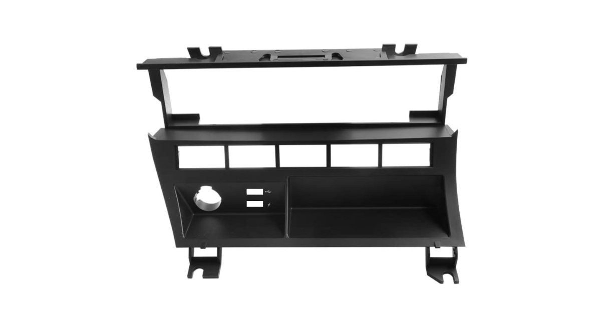
Automotive HVAC Bracket
Automotive · 4-cavity · PPAP Level 3
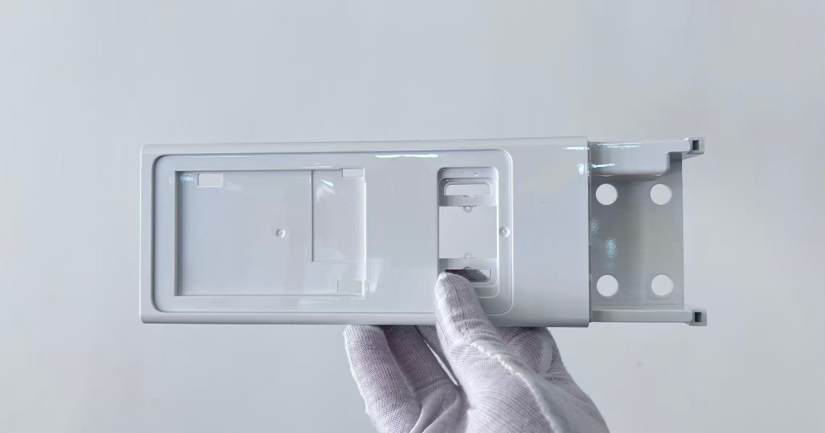
POS Monitor Support Bracket
Retail Equipment & POS · 1-cavity · 0.28mm flatness over 245mm
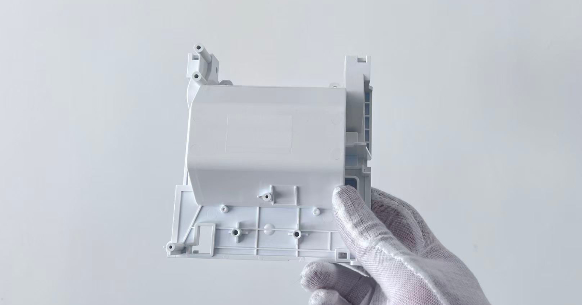
POS Printer Mounting Bracket
Retail Equipment & POS · 1-cavity · wall optimized 2.5→1.5mm
Blood Glucose Meter Support Bracket
Medical Devices · 2-cavity · 0.8mm wall · ±0.05mm
DFM for Injection Molded Structural Parts
The fifteen-point review our engineers run on every structural part before the tool is cut — from the load path to the final tolerance stack.
- 01 Load Requirements Load path, stress, and safety factor reviewed first
- 02 Wall Thickness Uniform sections sized to the material
- 03 Rib Thickness Rib-to-wall ratios that avoid sink and fill problems
- 04 Boss Design Boss-to-wall ratios and core-out geometry
- 05 Draft Angles Draft on walls, ribs, and bosses for clean release
- 06 Corner Radii Radii that reduce stress concentration
- 07 Undercuts Resolved with slides, lifters, or geometry changes
- 08 Parting Line Placement against function and appearance
- 09 Ejection Pin layout that avoids marking and distortion
- 10 Gate Location Fill balance, weld lines, and fiber orientation
- 11 Cooling Cooling layout for uniform shrinkage
- 12 Shrinkage Material-specific shrink compensation
- 13 Warpage Cooling, packing, and fiber effects analyzed
- 14 Critical Tolerances Feature-by-feature stack against mating parts
- 15 Assembly Requirements Fit and function checked against the mating assembly
Quality Control for Structural Plastic Parts
Structural parts are judged by the dimensions and the fit, so control is built around the features that decide both.
Critical Dimensions
The drawing's critical dimensions are identified before tooling and controlled by inspection plan — not checked at random.
Dimensional Consistency
Process capability is tracked on critical features through production — the fit doesn't drift between shipments.
First Article Inspection
T1 samples are inspected against the full drawing before production approval, with a documented report.
In-Process Inspection
In-process checks on critical features during production — dimension control while the parts are running.
Mold Trial Verification
T1 and T2 trials verify the tool against the drawing and the assembly — before production quantities are molded.
Material Traceability
Resin grade and lot are recorded per production run — traceable to the material certificate.
Cavity-to-Cavity Consistency
On multi-cavity tools, parts from every cavity are checked against each other so assemblies don't depend on which cavity the part came from.
Assembly Fit
Where mated samples are available, the part is checked against its counterpart — the only test that proves the interface works.
What Affects the Cost of Plastic Structural Parts?
Tooling, part, and secondary-operation cost drivers on structural programs.
Tooling Cost
- ✓Cavity count
- ✓Part geometry and size
- ✓Sliders and lifters
- ✓Inserts
- ✓Tolerance requirements
- ✓Steel selection
- ✓Hot runner system
- ✓Mold life requirements
Part Cost
- ✓Resin and grade
- ✓Part weight
- ✓Cycle time
- ✓Cavity count
- ✓Machine size
- ✓Production volume
Secondary Operations
- ✓Insert installation
- ✓Assembly
- ✓Painting
- ✓Printing
- ✓Inspection
- ✓Packaging
What Do We Need to Quote Your Structural Plastic Part?
The mechanical requirement drives material, geometry, and process selection — tell us what the part carries and how it locates, not just what it looks like.
Part & Drawing
- ✓3D CAD file (STEP or IGES)
- ✓2D engineering drawing
- ✓Plastic material and grade
- ✓Critical dimensions
- ✓Tolerance requirements
- ✓Surface finish
Production & Function
- ✓Annual volume
- ✓Expected mold life
- ✓Assembly requirements
- ✓Metal inserts, if any
- ✓Target market and application
- ✓Existing mold information, if transferring a tool
Our engineering team can review the part geometry and identify potential molding, tooling, material, and cost considerations before production.
Plastic Structural Parts Manufacturing FAQ
Procurement and engineering questions we answer most often on structural part programs.
What are plastic structural parts?
Plastic structural parts are functional components designed to support, position, connect, reinforce, or carry loads within a product or assembly. Unlike cosmetic housings and covers, they are engineered around mechanical performance, dimensional stability, and assembly requirements — structural frames, support parts, reinforcement parts, mounting components, and internal mechanisms. Structural brackets are one family within this category, covered on our plastic brackets page.
What plastics are commonly used for structural components?
PA and PA-GF for strength and stiffness, POM for moving and wear surfaces, PC for impact resistance, PC/ABS where strength and surface quality are both needed, PBT and PBT-GF for parts near electronics, PP for lightweight parts, and PEEK for high-temperature and chemical applications. Recent structural programs ran PA66-GF30 for an automotive HVAC bracket, PC+ABS for a POS monitor support bracket, and PC + 20% GF for a printer mounting bracket. JBRplas molds from a library of 500+ qualified grades.
Can you manufacture load-bearing plastic components?
Yes. Load-bearing parts are designed along the load path — wall and rib geometry, stress concentration, and material are evaluated together, with safety factor reviewed against the service condition. Documented examples include a PA66-GF30 automotive HVAC bracket qualified for -40°C to +110°C continuous temperature and 30G vibration, and a 0.8mm-wall medical support bracket holding ±0.05mm on critical dimensions.
Can JBRplas make structural parts with metal inserts?
Yes. Threaded inserts, bushings, and shafts can be insert-molded directly in the tool or installed in a controlled secondary step, depending on the feature and the volume. Insert molding is the usual choice where the insert position is critical to the assembly; our overmolding and insert molding service page covers when each approach is specified.
Can you manufacture high-volume structural components?
Yes — 27 injection molding machines from 90T to 650T, running multi-cavity tools up to 16 cavities. Current structural programs run at 280,000 pieces per year for the automotive HVAC bracket and 500,000 per year for a blood glucose meter support bracket. For long-running programs we build production tooling around the annual volume and the mold life the program requires.
Can you make multi-cavity molds for structural parts?
Yes — 4, 8, and 16-cavity tools with balanced filling, so parts from every cavity assemble the same. On structural programs the cavity count follows the annual volume and the tolerance: tight-tolerance parts are often run in lower cavitation for better process control, while established high-volume parts move to higher cavitation to reduce part cost. The multi-cavity mold manufacturing page covers the tooling side.
How do you reduce warpage in structural plastic components?
Warpage is managed before the tool is cut: cooling layout, gate location, packing profile, material shrinkage, and fiber orientation are analyzed against the part geometry — long parts, large thin areas, and asymmetric sections get the most attention. On an automotive HVAC bracket with a 180mm unsupported span, a previous supplier failed PPAP with up to 1.2mm distortion after ejection; after the cooling layout and pack profile were reworked, warpage measured 0.14mm against a 0.30mm limit.
What files are required for a structural plastic part quote?
A 3D CAD file (STEP or IGES), a 2D drawing with tolerances and critical dimensions, the plastic material and grade, annual volume, expected mold life, assembly requirements, and any metal insert requirements. If you are transferring an existing tool, send the existing mold information as well. Our engineering team reviews the geometry and identifies molding, tooling, material, and cost considerations before quoting.