Custom Plastic Connector Manufacturer
Precision injection molded connector housings and plastic components for electronics, automotive, industrial, medical, and electrical applications.
JBRplas focuses on precision plastic molding for connector housings and components. Metal terminals and contacts can be supplied as customer-provided or project-specific inserts where applicable.
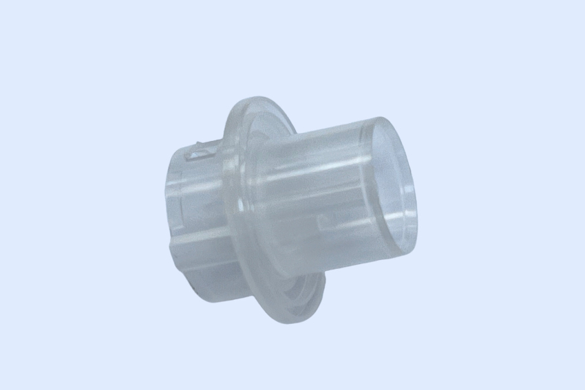
Precision Plastic Connector Manufacturing
Six areas of a connector program — from dimensional control and tooling to material selection and volume production.
Tight Dimensional Control
Connector performance is set by cavity dimensions, pitch, alignment, and mating dimensions. These features are identified during DFM, machined into the tool, and controlled in production — not just verified at first article.
Multi-Cavity Tooling
Connector components are usually high-quantity parts. Multi-cavity tooling can reduce piece cost for high-volume connector components, with balanced filling so every cavity produces a dimensionally identical part.
Precision Molding
Tight-tolerance molding supported by CMM inspection and production SPC on the dimensions the connector has to meet.
Insert Molding
Where a program uses metal pins, terminals, or threaded inserts, insert molding places them in the tool and molds the plastic body around them — no secondary assembly step.
Engineering Plastics
Material selection follows the electrical, mechanical, and thermal requirements of the application — from PBT and PA to PPS, PEEK, and LCP.
High-Volume Production
27 injection molding machines from 90T to 650T running multi-cavity tools on long-run connector programs, with documented process capability.
Types of Plastic Connector Components We Manufacture
Typical connector components include the families below. The applications listed reflect the part families we tool and mold — not a catalog.
| Component Type | Function & Typical Applications |
|---|---|
| Connector Housings | The molded body that carries the contacts and defines the connector's external form — electronics · automotive · industrial equipment |
| Plug Housings | The mating half that inserts into the receptacle — cable assemblies · device connectors |
| Socket Housings | The receptacle side that receives the plug — board-mounted connectors · panel connectors |
| Terminal Housings | Bodies that hold and position terminals inside the housing — multi-pin connectors · wire harnesses |
| PCB Connector Housings | Bodies molded for board mounting and reflow or through-hole assembly — board-level connectors |
| Wire-to-Board Connector Housings | Housings that align a wire-side connector to its board-side counterpart — control boards · sensor connections |
| Wire-to-Wire Connector Housings | Housings that lock two cable-side connectors together — wiring harnesses · cable assemblies |
| Cable Connector Components | Molded bodies and strain-relief features for cable terminations — cable assemblies · sensor cables |
Plastic Connector Components for Different Industries
Where the connector components we mold are used, with the applications typical for each industry.
Automotive
Connector components for vehicle electrical and electronic systems.
Typical applications: automotive connectors · sensor connectors · control module connectors · wiring connectors
Electronics
Connector components for electronic devices, boards, and modules.
Typical applications: PCB connectors · cable connectors · board-to-board connectors · device connectors
Industrial Equipment
Connectors for controls, sensors, and automation equipment.
Typical applications: sensor connectors · control connectors · automation equipment connectors
Medical Devices
Connector components for medical equipment and devices.
Typical applications: medical equipment connectors · sensor connectors · internal electrical connectors
Consumer Electronics
Connector components for consumer devices and their cables.
Typical applications: charging connectors · cable connectors · device connectors
Plastic Connector Design Considerations
Connector parts are small, functional, and tolerance-driven. Design decisions here are about mating, positioning, and release — not appearance.
Dimensional Accuracy
Connector performance is set by cavity dimensions, pitch, alignment, mating dimensions, and terminal positioning. Small dimensional variations can affect mating performance and assembly, so the critical dimensions are identified during DFM and controlled through the production run.
Terminal Cavity Design
Where the housing carries metal terminals, cavity geometry, terminal retention, terminal alignment, insertion direction, core design, and ejection all have to work together. Core pins form the cavities, and how they are supported in the mold decides how consistently the terminals seat.
Locking Features
Locking tabs, clips, latches, and retention features keep the connector mated under vibration and cable load. The locking structure has to balance retention force, assembly force, and material properties — a latch stiff enough to hold is often stiff enough to crack during assembly.
Mating Interface
The mating interface decides alignment, insertion force, mating clearance, dimensional consistency, and repeatability. These dimensions cannot be judged without the mating part, which is why the mating connector is part of the DFM review.
Draft Angle
Connector bodies carry many cavities, cores, and small features that all resist release. Draft is balanced against cavity geometry, texture, dimensional requirements, and tool life — and applied consistently on walls, ribs, and core-pin features.
Ejection
Connector parts are small, thin-walled, and complex — the hardest case for ejection. Ejector pin placement and core pins are planned so parts release without deformation, and so no ejector mark lands on a mating surface or inside a terminal cavity.
Thin Walls & Small Features
For connector designs with thin walls or small features, filling behavior, venting, mold temperature, gate design, and material selection require careful evaluation. These features are where short fills and warp start, so they are reviewed feature by feature during DFM.
Mold Flow & Venting
Terminal cavities and tight cores trap air and split the melt front. Filling balance, air traps, weld lines, and venting are analyzed before the tool is cut, so gas escapes and flow fronts rejoin where they do the least harm.
Materials for Injection Molded Connector Components
Material selection depends on temperature, electrical requirements, mechanical load, dimensional stability, chemical exposure, and production requirements. These are the families we run most for connector components.
| Material | Typical Considerations |
|---|---|
| PBT | Dimensional stability and electrical applications |
| PA / Nylon | Mechanical performance and toughness |
| PA-GF | Higher stiffness — glass content also changes shrinkage and anisotropy |
| PC | Impact resistance |
| PC/ABS | Balance of mechanical properties and appearance |
| PPS | High-temperature and chemically demanding applications |
| PEEK | High-performance applications |
| LCP | Precision, high-flow electrical connector applications |
Plastic Material Selection for Electrical Connector Components
A connector housing is part of the electrical system, so material selection goes beyond mechanical properties.
Insulation Requirements
The housing insulates contacts from each other and from the outside. Wall sections, creepage and clearance distances, and the dielectric strength of the material all matter where voltage is involved.
Temperature Resistance
Continuous service temperature — and soldering exposure, for board-mounted connectors — narrows the material list quickly. A housing that softens in service loses terminal retention.
Dimensional Stability
A housing that moves after molding does not mate reliably. Low-shrinkage, low-creep grades hold pitch and cavity dimensions through temperature cycling and over time.
Flame-Retardant Grades
Many electrical and electronic programs specify UL94 V-0 grades. Flame retardants change how the material processes — higher viscosity, a narrower processing window, and more gas in the cavity — and the process is set up around that behavior.
Chemical Resistance
Contact cleaners, fluxes, lubricants, and environmental exposure can attack a housing. Chemical compatibility is checked against the materials the connector meets in assembly and in service.
Final material and compliance requirements are specified according to the customer's application and the applicable industry standards. Tell us the standard the part has to meet, and we mold to the grade that carries it.
Injection Mold Design for Plastic Connector Components
How the mold is built around the part's critical features — the decisions that decide whether cavity-to-cavity consistency holds at volume.
- 01 Core Pins Form terminal cavities and small holes; support and cooling drive the layout
- 02 Cavity Inserts Carry the tight features and can be replaced individually
- 03 Slides & Lifters Form retention features and side openings that block release
- 04 Gate Design Sets fill balance, weld line position, and how the melt meets delicate cores
- 05 Cooling Designed against the part's shape — uneven cooling is what warps small parts
- 06 Venting Vents placed where air traps form around core pins and terminal cavities
- 07 Ejection Planned on internal surfaces so mating faces stay clean
- 08 Multi-Cavity Balance Cavity-to-cavity consistency, held across the whole tool
Connector Injection Molding Technologies
Depending on connector geometry, tolerance, and volume, we select the tooling and molding approach that fits the program.
Precision Injection Molding
The core capability — tight-tolerance molding with CMM inspection and SPC on critical connector dimensions.
Multi-Cavity Molds
4, 8, and 16-cavity tools with balanced filling so parts from every cavity meet the same dimensional target.
Hot Runner Molds
Reduce runner waste and improve production efficiency on high-volume connector parts.
Insert Molding
Metal pins, terminals, and threaded inserts molded into the housing in one cycle.
Automated Production
Where volume supports it, automated production reduces cycle-to-cycle variation and labor content.
High-Volume Manufacturing
Long-run production on 27 machines from 90T to 650T, with process capability documented.
Dimensional Control for Connector Components
Connector parts are judged by dimensions that have to hold shot after shot — so inspection is planned around the features the connector has to meet.
First Article Inspection
Critical dimensions measured against the drawing on T1 samples — cavity by cavity, before production release.
CMM Inspection
Mating dimensions, pitch, and terminal positions measured on a coordinate measuring machine — the features a caliper cannot verify.
Production SPC
Critical dimensions monitored with statistical process control through the production run, with documented capability.
In-Process Inspection
Dimensional and visual checks at defined intervals during molding — flash, short fills, and ejector marks caught at the press, not at the customer.
Documentation
Inspection reports, material certificates, and process records shipped with the parts, per the program's requirements.
Fit Verification
Where assembled samples are available, the housing is checked against its mating part — the only test that proves the interface works.
ISO 9001 and ISO 13485 quality systems. Cleanroom molding is available for medical connector programs.
Related Precision Plastic Component Case Studies
This is not a connector housing. It is the closest published program to connector work — insert-molded pins, tight tolerances, and multi-cavity production.

What Determines Plastic Connector Cost?
Connector cost concentrates in the mold — core pins, cavity count, and precision features — before piece price is set by material and cycle time.
Tooling Cost
- ✓Cavity count
- ✓Core pins and cavity inserts
- ✓Slides and lifters
- ✓Hot runner system
- ✓Mold steel selection
- ✓Tolerance requirements
Part Cost
- ✓Material and grade
- ✓Part weight
- ✓Cycle time
- ✓Cavity count
- ✓Automation
Secondary Operations
- ✓Insert assembly
- ✓Terminal insertion
- ✓Marking
- ✓Inspection
What We Need to Quote Your Plastic Connector
A connector cannot be quoted from its own drawing alone — the mating component decides which dimensions are critical.
Part & Drawing
- ✓3D CAD file (STEP or IGES)
- ✓2D drawing with tolerances
- ✓Material specification
- ✓Critical dimensions and tolerance requirements
- ✓Surface finish
- ✓Applicable standards
Production & Interface
- ✓Annual volume
- ✓Mating connector or mating component information
- ✓Terminal specification
- ✓Insert requirements
- ✓Assembly method
The mating component matters more on this part family than on any other — many housing dimensions cannot be judged without the part it mates with. Send the mating connector's drawing or 3D file if you have it.
Plastic Connector Manufacturing FAQ
Procurement and engineering questions we answer most often on connector programs.
What plastic materials are commonly used for connector housings?
PBT, PA, PA-GF, PC, PC/ABS, PPS, PEEK, and LCP cover most connector housing programs — chosen for dimensional stability, electrical behavior, temperature, mechanical load, and the assembly process. PBT and PA are the workhorses of connector housings; PPS, PEEK, and LCP come in where temperature or precision demands more. JBRplas molds from a library of 500+ qualified grades.
Can you manufacture precision connector housings?
Yes — precision molding is the core capability behind this page. Critical dimensions such as pitch, mating dimensions, and terminal positions are identified during DFM, machined into the tool, and verified with CMM inspection and production SPC. As a reference point from a comparable program: a 16-cavity PC tool running a precision housing holds ±0.05mm, with a cavity-to-cavity weight Cpk of 1.52.
Can JBRplas manufacture multi-cavity connector molds?
Yes — we build multi-cavity tools up to 16 cavities, with balanced manifolds, independent cooling, and cavity-to-cavity weight validation during process qualification. Multi-cavity tooling is how piece cost comes down on connector components, which are usually high-quantity parts.
Can connector housings include metal inserts?
Yes — threaded inserts, bushings, and pins can be molded into a connector body by insert molding, so no secondary assembly step is needed. The inserts are loaded into the tool and the plastic is molded around them, with a locating system that holds each insert to position during injection.
Can you mold around metal terminals?
Yes. Where terminals or pins are customer-supplied or project-specific, they can be overmolded as inserts. A published example: a 4-cavity ABS insert mold that carries five 1.6mm metal pins per part. Each pin is held by dedicated locating inserts at both the seat and the tip, and the runner was balanced with Moldflow so melt pressure wraps each pin symmetrically instead of pushing it sideways.
What tolerances can be achieved for plastic connector components?
Tolerance depends on part size, feature, material, and mold design, so it is set feature by feature during DFM rather than quoted as a single number. Where a program requires it, we hold ±0.05mm on critical dimensions and verify with CMM and SPC. The published reference: a 32.8mm precision housing molded in a 16-cavity tool held all critical dimensions within ±0.04mm in production, at 2,500,000 pieces per year.
Can you manufacture high-volume connector components?
Yes — 27 injection molding machines from 90T to 650T running multi-cavity tools on long-run programs, with documented process capability. High-volume programs have run at 2,500,000 pieces per year from a single 16-cavity tool.
Can you provide connector housing DFM analysis?
Yes — DFM review is part of every quotation. We review wall thickness, draft, core-pin and cavity layout, gating, ejection, venting, and the tolerance stack against the mating part, then report the issues that would affect tooling cost, cycle time, or part quality before the mold is cut.
Do you manufacture the metal terminals as well?
No — JBRplas focuses on plastic injection molded connector housings and components. Metal terminals and contacts are handled according to the specific project scope and customer-supplied requirements: typically supplied by the customer and insert-molded into the housing. This is the one scope point worth confirming before a connector RFQ.