Project Overview
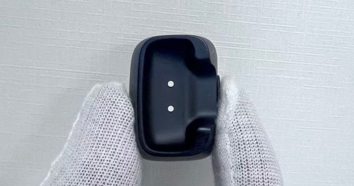
A consumer electronics brand required a production mold for a wireless microphone magnetic charging dock housing — a precision micro-component measuring 30 × 20 × 10 mm at just 2 grams. The part’s diminutive scale concentrates multiple manufacturing challenges: 0.8 mm thin-wall sections must fill completely before the flow front freezes, while the Class A cosmetic surface demands zero sink marks, weld lines, or flow marks on an area where every defect is visible to the naked eye. The 4-cavity configuration compounds these requirements — a 0.01 g weight variation represents a 0.5% shift on a 2 g part.
Part Specifications
| Parameter | Specification |
|---|---|
| Product | Wireless microphone magnetic charging dock housing |
| Dimensions | 30.0 × 20.0 × 10.0 mm |
| Weight | 2.0 g |
| Material | PC+ABS (engineering grade) |
| Wall thickness | 0.8–1.2 mm |
| Cavities | 4 |
| Surface class | Class A cosmetic (visible exterior) |
| Surface requirements | Zero sink marks, zero weld lines, zero flow marks, uniform gloss |
| Application | Consumer electronics — wireless microphone charging base |
Engineering Approach
DFM Draft Angle Optimization
The original part design specified draft angles of 0.5° on the exterior walls — a value that, while functional for ejection, is marginal for a Class A cosmetic surface on a PC+ABS part. At 0.5° draft with a 10 mm draw depth, the dimensional difference between the top and bottom of the exterior wall is approximately 0.09 mm — tight enough that any microscopic drag during ejection produces a visible scuff on the cosmetic surface.
JBRplas’s DFM analysis identified two improvements:
Exterior wall draft increased to 1.0°. The additional 0.5° of draft increases the top-to-bottom dimensional difference to approximately 0.17 mm, providing a wider ejection clearance that eliminates drag-induced surface scuffing. The 1.0° draft is well within the cosmetic acceptability range for a part of this size — the visual taper is imperceptible on a 30 × 20 mm footprint.
Rib draft increased to 2.0°. The internal snap-fit retention ribs, originally designed at 0.5° draft, were increased to 2.0°. The steeper draft serves two purposes: it ensures clean rib ejection without deformation (critical for snap-fit function in a part this small), and it reduces the localized ejection force at the rib roots — the area most susceptible to sink-mark formation on the opposite cosmetic surface.
Gate Design for Micro Cosmetic Parts
Gate selection for a 2-gram cosmetic part involves balancing three competing requirements: the gate must be large enough to fill the cavity before the melt freezes, small enough to leave a minimally visible vestige on the Class A surface, and positioned so that the resulting weld line — if unavoidable — falls on a non-cosmetic surface.
JBRplas selected a pin gate with a 0.6 mm diameter positioned on the internal (non-cosmetic) face, near the geometric center of the part. The rationale:
0.6 mm diameter is the minimum that provides adequate flow area for the 2 g shot weight in PC+ABS. Below 0.5 mm, the shear rate at the gate exceeds the material’s critical shear threshold, producing molecular degradation at the gate region and visible silver streaking on the adjacent cosmetic surface. Above 0.8 mm, the gate freeze time extends beyond the holding pressure window, leaving a gate vestige that requires manual trimming — unacceptable for a 4-cavity production tool at this cycle time.
Center-gate on the internal face places the gate on the side of the part that is hidden after assembly. The melt flows from the center outward in all directions, producing a radial fill pattern. For a rectangular part with a central aperture (the magnetic charging pin opening), the flow splits around the core pin forming the aperture, then re-joins on the opposite side. JBRplas oriented the gate such that the weld line from this flow-front reunion falls on the internal face — invisible to the end user.
Gate recess of 0.05 mm creates a controlled break point that ensures the gate separates cleanly at the part surface during ejection. The resulting vestige height is below 0.05 mm — substantially below the 0.1 mm threshold where vestige becomes visually detectable on a part of this size.
Cooling System Design
Uniform cooling is the foundation of uniform gloss on a cosmetic PC+ABS surface. Differential cooling rates across the part surface produce differential shrinkage, which manifests as gloss variation — faster-cooling regions develop a slightly higher gloss than slower-cooling regions, creating a visible patchiness on the surface under directional lighting.
For this 4-cavity mold, JBRplas implemented:
Independent cooling circuits per cavity. Each of the four cavities has its own water circuit with independent flow control, ensuring that cavity-to-cavity cooling rate variation is within ±1°C. At this level of thermal uniformity, the gloss difference between parts from different cavities is below the threshold of visual detection under 800-lux inspection lighting.
Baffle-enhanced cooling in the core. The core side, which forms the internal geometry including ribs and bosses, has higher thermal mass than the cavity side. Baffle-type cooling channels were machined into the core inserts to increase the coolant dwell time in the core, compensating for the higher heat load and bringing the core surface temperature to within 2°C of the cavity surface temperature.
Mold temperature maintained at 65 ± 3°C. PC+ABS for cosmetic applications requires a mold temperature high enough that the melt replicates the polished cavity surface before the skin solidifies, but low enough to maintain an economical cycle time. At 65°C, the melt skin remains above the glass transition temperature long enough for full surface replication, while the 3°C tolerance band ensures gloss consistency shot-to-shot and cavity-to-cavity.
Mold Polishing for Class A Cosmetic Surface
The cavity surface finish directly determines the part surface finish. For a Class A cosmetic PC+ABS part requiring uniform gloss with zero flow marks, the cavity must be polished to a level where the surface roughness is substantially below the wavelength of visible light — any microscratch or polishing line on the cavity surface is faithfully replicated on every molded part.
JBRplas specified an SPI A1 mirror polish for all four cavity surfaces:
Polishing progression: The cavities were polished through a graded sequence — 400 → 600 → 800 → 1200 grit diamond paste, followed by 3-micron and then 1-micron diamond compound for the final mirror finish. Each grade removes the scratches left by the previous grade, with the 1-micron compound producing a surface roughness of Ra ≤0.025 μm.
Post-polish inspection: Each cavity was inspected under 20× magnification with directional lighting to verify the absence of micro-scratches, pitting, or grain-boundary relief on the S136 steel surface. Any cavity that showed a detectable polishing line at 20× was reworked until the surface was optically featureless.
S136 steel selection for polishability: S136 (420 stainless, electroslag-remelted) was selected for its combination of corrosion resistance and polishability. The ESR process produces a homogeneous microstructure free of the inclusions and voids that create pits during mirror polishing. At 48–52 HRC, the steel is hard enough to maintain the mirror finish across the 300,000-shot tool life without re-polishing.
Injection Molding Process Parameters
| Parameter | Value |
|---|---|
| Material | PC+ABS, engineering grade |
| Barrel temperature | 245–255°C (zoned: 230/240/250/255/250°C) |
| Mold temperature | 65 ± 3°C |
| Injection speed | Medium-high (80–100 mm/s) |
| Injection pressure | 900–1,100 bar |
| Holding pressure | 45–55% of injection pressure |
| Holding time | 3–4 s |
| Cooling time | 8–10 s |
| Total cycle time | 18–22 s |
| Material drying | 80°C × 4 hours, moisture <0.02% |
The injection speed is set at the upper end of the medium range — fast enough to fill the 0.8 mm thin-wall sections before the flow front freezes, but not so fast that shear heating at the gate produces silver streaks or material degradation. At 80–100 mm/s fill speed, the cavity fills in approximately 0.4–0.6 seconds — well within the freeze-off window for PC+ABS at this wall thickness.
The holding pressure of 45–55% with a 3–4 second hold time addresses the primary cosmetic risk: sink marks at the rib roots on the internal face telegraphing through to the visible exterior surface. The short hold time, relative to larger parts, reflects the rapid cooling of a 2g part — the gate freezes within 3–4 seconds, after which additional hold pressure has no effect. The holding pressure magnitude is set to pack out the volumetric shrinkage at the rib roots without over-packing the thin sections, which would create residual stress and increase the risk of warpage after ejection.
Cavity Balance Verification
For a 4-cavity mold producing cosmetic parts at 2g each, cavity-to-cavity weight variation is the primary indicator of fill balance. A weight difference between cavities means a difference in packing density, which means a difference in shrinkage, which means a difference in dimensions and surface appearance.
JBRplas verified cavity balance through Moldflow simulation prior to steel cutting, then confirmed through short-shot progression during T1:
- Moldflow prediction: Fill imbalance <2% between the fastest and slowest cavities
- T1 short-shot verification: All four cavities reached 95% fill within 0.03 seconds of each other
- Production weight consistency: Cavity-to-cavity weight variation <0.008g (0.4% of part weight)
Mold Design Details
| Parameter | Detail |
|---|---|
| Mold type | Two-plate injection mold |
| Cavities | 4-cavity |
| Mold steel | S136 (48–52 HRC) |
| Runner system | Cold runner, naturally balanced |
| Gate type | Pin gate, 0.6 mm diameter, 0.05 mm recess |
| Gate location | Internal face, geometric center |
| Cooling | Independent circuits per cavity, baffle-enhanced core |
| Cavity surface finish | SPI A1 mirror polish (Ra ≤0.025 μm) |
| Ejection | Blade ejectors on perimeter, ejector pins on internal ribs |
| Venting | 0.02 mm perimeter vent, 0.015 mm at flow-front meeting points |
| Draft angles | 1.0° exterior walls, 2.0° internal ribs |
| Mold life | 300,000 shots |
Quality Control
- Surface appearance — 100% visual inspection under 800-lux directional lighting; zero tolerance for sink marks, weld lines, flow marks, or gloss variation on the visible exterior face
- Dimensional inspection — CMM measurement on 1:100 sampling; overall dimensions verified against 30.0 ± 0.05 × 20.0 ± 0.05 × 10.0 ± 0.05 mm
- Weight consistency — Shot-to-shot weight variation <0.5% (0.01g on 2g part); cavity-to-cavity weight variation <0.4%
- Gloss uniformity — Gloss meter measurement at 60° geometry on 1:50 samples; gloss variation <2 GU across the visible surface
- Gate vestige — Profile measurement on 1:50 samples; vestige height ≤0.05 mm above surface
- Assembly fit — Functional test with mating magnetic charging pins and base plate on 1:100 samples
Results
| Metric | Target | Achieved |
|---|---|---|
| Surface appearance (cosmetic) | Zero defects | ✅ Pass, all cavities |
| Dimensional tolerance | ±0.05 mm | Cpk = 1.52 |
| Cavity-to-cavity weight variation | <0.5% | 0.32% |
| Gloss uniformity (60°) | <3 GU variation | 1.4 GU |
| Gate vestige height | ≤0.05 mm | 0.03 mm average |
| Cycle time | ≤24 s | 20 s |
| First-pass yield | >97% | 98.6% |
| T1 lead time | 25 days | 22 days |
The integrated approach — DFM draft optimization, center pin-gate on the internal face, SPI A1 mirror-polished cavities, and independently cooled 4-cavity layout — delivered a cosmetic surface that met the brand’s Class A requirement across all production cavities. The 0.32% cavity-to-cavity weight variation on a 2g part confirmed that the naturally balanced runner and independent cooling circuits provided the thermal and flow uniformity needed for consistent cosmetic quality in precision micro-molding.
The 20-second cycle time from a 4-cavity mold delivers approximately 720 parts per hour — sufficient throughput for the client’s consumer electronics production volume with capacity for seasonal demand fluctuation.
This case study demonstrates JBRplas’s precision micro-molding capability for consumer electronics cosmetic parts — including DFM draft angle optimization for Class A surfaces, pin-gate design for sub-0.05mm vestige control, SPI A1 mirror polishing on S136 cavities, baffle-enhanced independent cavity cooling for gloss uniformity, and 4-cavity fill balance within 0.32% on a 2-gram part.