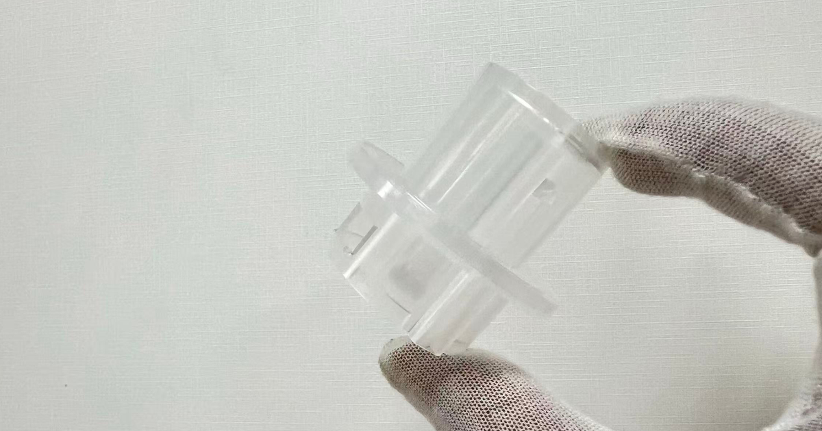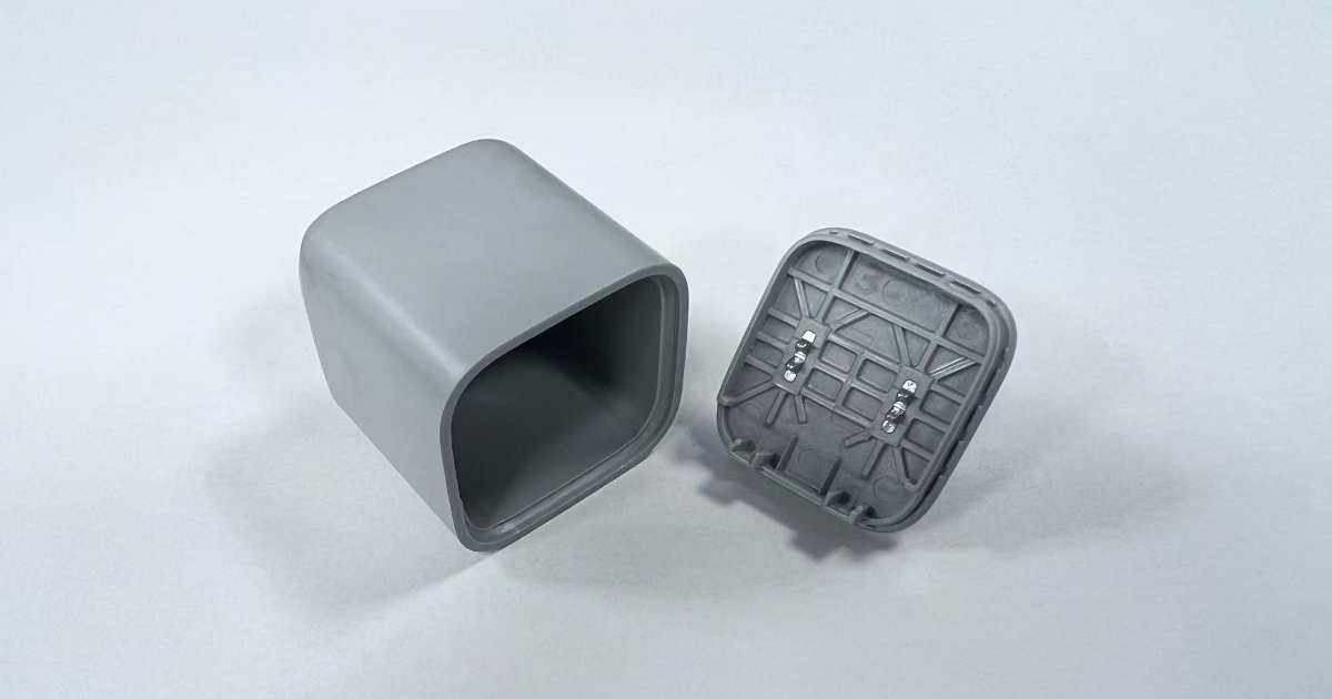
Project Overview
A consumer electronics manufacturer developing a next-generation USB Type-C mini charger required a production mold for the charger housing — a compact two-piece enclosure consisting of an upper shell and lower shell joined by ultrasonic welding. The housing is a consumer-facing product sold in domestic and international markets, requiring CCC (3C) certification for the Chinese market alongside RoHS and REACH compliance for export.
The part appears simple — a 32.8mm cube-like enclosure with a clean exterior — but the combination of 0° draft angles, PC flame-retardant material, 16-cavity production, and Class A cosmetic surfaces on a compact, thin-walled part creates a set of interacting constraints that make this one of the more demanding production molds in the consumer electronics category.
Challenge: PC (polycarbonate) with UL94 V-0 flame-retardant rating is thermally sensitive, moisture-sensitive, and highly viscous compared to unfilled ABS or PP. Running it in a 16-cavity hot runner configuration at a 20-second cycle — while maintaining ±0.05mm tolerance, cavity-to-cavity weight variation under ±0.05g, and Class A cosmetic surfaces with zero sink marks, weld lines, or burn marks — required precision hot runner balancing, aggressive venting, mirror-polished cavities with near-zero draft, and multi-circuit independent cooling.
Part Specifications
| Parameter | Specification |
|---|---|
| Product | USB Type-C mini charger housing (upper + lower shell) |
| Dimensions | 32.8 × 32.0 × 32.0 mm |
| Part weight | 10.55 g |
| Material | PC, UL94 V-0 flame-retardant grade |
| Color | Grey |
| Wall thickness | 2.4 mm nominal |
| Surface finish | Mirror polish (exterior) + fine matte texture (anti-fingerprint) |
| Tolerance | ±0.05 mm |
| Assembly method | Ultrasonic welding (upper + lower shell) |
| Certifications | CCC (3C), RoHS, REACH |
| Flame rating | UL94 V-0 |
| Annual volume | 2,500,000 pieces |
Engineering Approach
16-Cavity Hot Runner Fill Balance
A 16-cavity mold multiplies every process variable by 16. A 2% flow imbalance that produces a barely measurable 0.2g variation in a single-cavity mold becomes a 3.2g variation across 16 cavities — enough to produce short shots on the slowest-filling cavities and flash on the fastest.
The YUDO hot runner system was specified with the following design requirements:
- Naturally balanced manifold geometry — every melt flow path from the machine nozzle to each cavity gate is identical in length, diameter, and number of turns. There is no artificially restricted runner or adjustable valve pin timing to compensate for geometric imbalance — the manifold is balanced by design.
- Valve gate sequencing — each of the 16 drops is individually controlled by a valve gate pin, allowing all 16 cavities to open and close simultaneously rather than sequentially. Sequential valve gating creates a cascade effect where the first cavity to fill begins cooling while the last cavity is still filling — producing cavity-to-cavity weight and shrinkage variation.
- Individual drop temperature control — each nozzle has an independent thermocouple and heater, allowing ±1°C temperature control at each gate. A 3°C temperature variation at the gate changes the melt viscosity enough to shift cavity fill time by several percent — enough to move the slowest cavity outside the weight tolerance.
Cavity-to-cavity weight variation was validated during process qualification: 16 cavities, 30 shots per cavity, 480 data points. Mean weight: 10.55g. Range: 10.52–10.58g. Standard deviation: 0.018g. All 16 cavities within ±0.05g — a Cpk of 1.52 on cavity weight balance.
PC V-0 Material Processing
Polycarbonate with UL94 V-0 flame-retardant additives presents specific molding challenges beyond standard unfilled PC:
Moisture sensitivity. PC absorbs moisture rapidly from ambient air — 0.15–0.35% by weight within 30 minutes of exposure. Processing PC at 280–310°C with residual moisture produces hydrolysis: the water molecules react with the polycarbonate chain, reducing molecular weight and creating voids, silver streaks, and surface splay on the molded part. The material was dried at 120°C for 4 hours in a desiccant dryer to <0.02% moisture content, with a closed-loop conveying system maintaining dry conditions from dryer to machine throat.
High melt viscosity. PC V-0 exhibits higher melt viscosity than unfilled PC due to the flame-retardant additives. This increases the injection pressure required to fill 16 cavities simultaneously and raises the risk of short shots in the farthest cavities or burn marks from gas trapped by the viscous melt front. We specified injection pressures of 90–130 MPa — within the capability of the 280T press but requiring the full available injection velocity to fill all 16 cavities before the gate freezes.
Narrow processing window. PC V-0 has a narrower melt temperature window than standard PC. At the low end (~280°C), the melt viscosity rises sharply and cavity fill becomes incomplete. At the high end (~310°C), the flame-retardant additives begin to degrade, producing gas, discoloration, and reduced mechanical properties. The process was locked at a melt temperature of 295°C ±5°C with a mold temperature of 105°C ±5°C — the center of the processing window where viscosity is manageable and additive degradation is minimal.
Zero-Draft Mirror Polish
The housing exterior walls have 0° draft — the walls are perpendicular to the parting line with no taper. This is a deliberate design decision for the product’s visual appearance: the charger is a small, monolithic-looking object on a desk or nightstand, and draft angles create visible taper lines at the parting line that break the visual continuity.
Zero draft creates a fundamental molding challenge: the part does not want to release from the cavity. Every micron of surface roughness on the cavity wall increases the ejection force required to strip the part. At some threshold, the ejection force exceeds the strength of the still-warm part, and the ejector pins punch through the part surface — a defect called ejector push-out or “pin push.”
The cavity surfaces were polished to SPI A-1 mirror finish (Ra ≤ 0.025 µm) — the highest polish grade achievable in injection mold manufacturing. The mirror finish serves two purposes:
- It minimizes the coefficient of friction between the PC part and the cavity steel during ejection, reducing the ejection force at the critical moment when the part is still above its glass transition temperature and has minimal mechanical strength
- It produces the high-gloss exterior surface the product design requires — a surface that is visually identical to the glass-fronted consumer electronics the charger sits alongside
The ejector system was designed with large-diameter, well-distributed ejector pins (8 pins per cavity, minimum Ø3mm) to keep ejection pressure per pin below the yield strength of the warm PC part. Ejector pin locations were engineered to push on internal surfaces only — ribs, bosses, and the parting plane — with zero ejector contact on any exterior cosmetic surface.
Ultrasonic Welding Assembly
The upper and lower shells are joined by ultrasonic welding — a process where high-frequency (20 kHz) mechanical vibration generates localized frictional heat at the joint interface, melting and fusing the two halves together in under one second. The ultrasonic welding process imposes additional dimensional requirements on the molded parts beyond the drawing tolerances:
- Joint flatness — the welding plane where the upper and lower shells meet must be flat to within ±0.03mm across the full 32mm perimeter. A gap larger than 0.05mm at any point on the joint line reduces the welding energy transfer efficiency and creates a weak or incomplete weld.
- Joint alignment — the upper and lower shells must align to within ±0.05mm edge-to-edge after welding. Misalignment creates a visible step at the parting line — unacceptable on a consumer-facing product.
- Energy director design — the molded-in triangular ridge (energy director) on the lower shell that focuses the ultrasonic energy at the joint must have a consistent height and apex radius across the full perimeter. Variation in the energy director geometry changes the weld time and strength.
The mold was designed with the welding plane as a datum surface, machined to ±0.01mm flatness, and verified on CMM before mold assembly. The energy director was formed by a precision-ground insert that could be replaced independently of the main cavity — allowing energy director geometry to be adjusted without re-cutting the entire cavity if welding process development required changes.
Venting for PC V-0
PC V-0 generates more gas during injection than unfilled PC — the flame-retardant additives release volatile compounds at processing temperature. Inadequate venting produces two failure modes:
- Burn marks — trapped gas compresses and auto-ignites at the end of fill, leaving black or brown carbonized marks on the part surface
- Silver streaks / splay — gas dissolved in the melt comes out of solution as the melt front advances, creating a frosted or silvery pattern on the surface
The venting strategy combined three approaches:
- Parting line vents — 0.015–0.02mm deep by 6mm wide channels at the end-of-fill locations predicted by mold flow analysis. Vent depth for PC is narrower than for lower-viscosity materials (0.02–0.03mm for PP/PE) to prevent flash while still allowing gas to escape.
- Ejector pin vents — the clearance between ejector pins and their bores (typically 0.01–0.02mm diametral) provides a secondary vent path. Pins were positioned at known gas trap locations — the last areas to fill — to double as venting points.
- Core vent pins — dedicated vent pins (3mm diameter, 0.015mm vent slot depth) were placed at the deepest points of the cavity where parting line vents are too distant to be effective.
Multi-Circuit Independent Cooling
A 16-cavity mold with a 20-second target cycle time requires cooling that is both fast and uniform. Each cavity must reach ejection temperature at the same time — if cavity #7 cools 2 seconds slower than the rest, the cycle time for all 16 cavities extends to accommodate cavity #7.
The cooling design incorporated:
- Four independent cooling circuits — two circuits for the cavity side (inner zone + outer zone) and two for the core side, each with dedicated flow control and temperature monitoring
- Circuit layout — cooling channels positioned 12–15mm from the cavity surface, Ø10mm diameter, with turbulent flow (Re > 10,000) in all circuits
- Individual circuit flow meters — allowing real-time verification that each circuit is receiving the specified coolant flow rate; a flow restriction in one circuit would produce a temperature gradient across the mold face that would show up as cavity-to-cavity dimensional variation
The 20-second cycle was achieved: 2.5s injection, 6s holding, 11s cooling, 0.5s mold open/eject/close.
Tooling Details
| Parameter | Detail |
|---|---|
| Mold type | Two-plate, 16-cavity, hot runner |
| Mold base | HASCO standard, 650 × 600 × 580 mm |
| Cavity steel | S136H, 48–52 HRC |
| Core steel | S136H |
| Mold base material | S50C |
| Hot runner system | YUDO, valve gate, 16 drops |
| Gate type | Valve gate, direct pin-point |
| Parting line | Central (mid-plane) |
| Venting | Parting line vents (0.015–0.02mm) + ejector pin vents + core vent pins |
| Cooling | Four independent circuits, Ø10mm, turbulent flow |
| Ejection | 8× Ø3mm ejector pins per cavity (internal surfaces only) |
| Cavity surface | SPI A-1 mirror polish + fine matte texture |
| Mold weight | 1,200 kg |
| Press size | 280T precision injection molding machine |
Injection Molding Process
| Parameter | Value |
|---|---|
| Machine | 280T precision injection molding machine |
| Clamp force | 220 Ton |
| Melt temperature | 280–310°C (set: 295°C) |
| Mold temperature | 90–120°C (set: 105°C) |
| Injection pressure | 90–130 MPa |
| Holding time | 5–8 s |
| Cooling time | 10–14 s |
| Total cycle time | 20 s |
| Material drying | 120°C × 4 h, desiccant dryer |
Timeline
| Stage | Duration |
|---|---|
| DFM review | 3 days |
| Mold design | 7 days |
| Hot runner specification (YUDO) | 5 days (parallel with design) |
| Steel procurement | 5 days (parallel with design) |
| CNC machining + EDM | 14 days |
| Polishing (SPI A-1, 16 cavities) | 4 days |
| Mold assembly | 2 days |
| T1 trial | 2 days |
| Process optimization | 3 days |
| Total lead time | 35 days |
Results
| Metric | Target | Achieved |
|---|---|---|
| Cavity weight variation (16-cavity) | ±0.05 g | ±0.03 g (Cpk = 1.52) |
| Dimensional tolerance | ±0.05 mm | All within ±0.04 mm |
| Surface finish (exterior) | SPI A-1 mirror, zero defects | Confirmed |
| Burn marks / silver streaks | Zero | Zero |
| Sink marks (exterior) | Zero | Zero |
| Ejector pin push-out | Zero | Zero |
| Weld line visibility (exterior) | None visible | None |
| Ultrasonic welding joint flatness | ±0.03 mm | ±0.018 mm |
| Cycle time | ≤22 s | 20 s |
| UL94 V-0 | Required | Certified (material + molded part) |
| T1 lead time | 38 days | 35 days |
| Production Cpk (critical dimensions) | ≥1.33 | 1.48 (mean across 6 critical dims) |
The mold entered production 7 weeks from project kickoff. At a 20-second cycle with 16 cavities, the mold produces approximately 2,800 parts per hour — 2.5 million parts per year on a 24/5 schedule. The client’s charger received CCC certification with the JBRplas housing documented in the certification submission. No field reports of housing defects — crack, deformation, discoloration, or weld failure — have been received in the production period to date.
This case study demonstrates JBRplas’s high-cavitation production mold capability for consumer electronics — including 16-cavity hot runner fill balancing, PC V-0 flame-retardant processing with zero burn marks, 0° draft SPI A-1 mirror polishing, ultrasonic welding joint precision, and CCC certification-ready process control (Cpk ≥ 1.33 maintained across all critical dimensions).