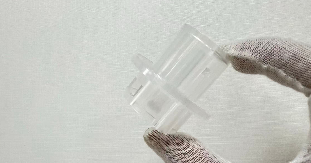
Project Overview
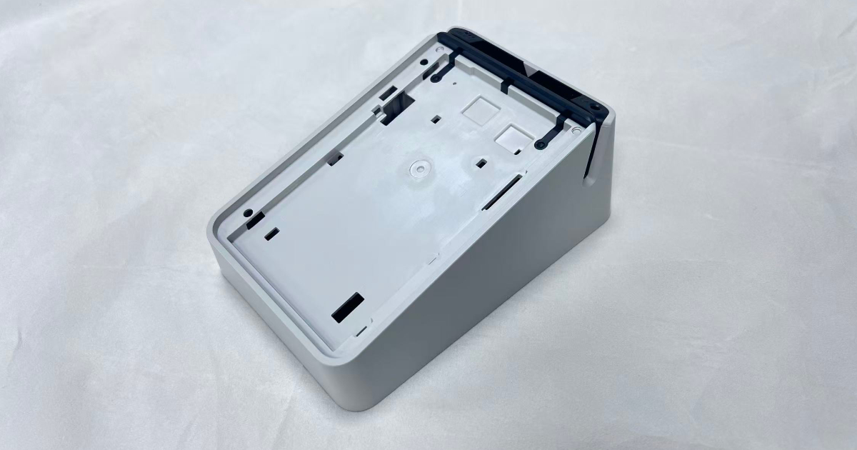
A UK-based payment terminal manufacturer developing a next-generation POS device for the European market required a production mold for the terminal housing — a two-shot injection-molded assembly combining a black PC card-reader track with a white PC UL V-0 main shell, middle partition, and internal rib structure. The complete assembly measures 106 × 146 × 56 mm and weighs 110 grams, serving as both the structural enclosure and the user-facing surface of a financial transaction device deployed in retail and hospitality environments across Europe.
The housing is not a simple enclosure. It integrates a precision card-reader guide rail in black PC, a white PC structural shell with 3 mm walls, a 1.5 mm middle partition that separates the electronics compartment from the card path, 1 mm reinforcement ribs for drop-impact rigidity, an insert-molded metal shielding plate and contact points overmolded into the middle partition, and an integrated speaker grille on one side for audible transaction feedback. Each of these features must be produced in a single two-shot rotary mold cycle.
A POS terminal housing carries compliance obligations that consumer electronics do not. The white PC material must meet UL V-0 flame retardancy — a requirement for financial terminals installed in commercial environments where electrical safety standards are enforced by payment network certification bodies. The card-reader guide rail must maintain ±0.2 mm dimensional accuracy across the swipe path to ensure reliable magnetic stripe reading. The metal shielding insert, overmolded into the partition, must maintain electrical continuity to ground with no plastic flash encroaching on the contact surface.
Part Specifications
| Parameter | Specification |
|---|---|
| Product | POS payment terminal housing assembly |
| Client location | United Kingdom |
| Dimensions | 106.0 × 146.0 × 56.0 mm |
| Weight (complete assembly) | 110 g |
| Housing wall thickness | 3.0 mm |
| Middle partition thickness | 1.5 mm |
| Rib thickness | 1.0 mm |
| First shot (black) | PC — card reader guide rail |
| Second shot (white) | PC UL V-0 — main shell, partition, ribs |
| Metal inserts | Shielding plate + contact points (overmolded) |
| Special features | Integrated speaker grille on side wall |
| Application | Payment terminal, financial POS |
Engineering Approach
Two-Shot Mold Strategy — Why Not Two Separate Molds?
The client initially considered producing the black card-reader track and the white housing shell as two separate injection-molded components, assembled with screws or snap-fits during final assembly. This approach would have simplified the mold design — two independent single-shot molds with no rotary platen requirement — but it introduced three problems that made it unsuitable for a financial terminal:
Card path alignment. The magnetic stripe reader track requires a continuous, uninterrupted surface with a dimensional tolerance of ±0.2 mm across the entire swipe length. A separate black track component, however precisely molded, introduces assembly tolerance stack-up — the track must be aligned to the shell, the shell must be aligned to the PCB, and the PCB must be aligned to the card slot opening. Each interface adds 0.05–0.10 mm of positional uncertainty. A two-shot mold forms the black track and white shell as a molecularly bonded single component, eliminating three assembly interfaces and their associated tolerance accumulation.
Ingress protection. POS terminals in retail environments are exposed to spilled drinks, condensation from cold-counter placement, and cleaning fluids used on shop counters. A two-part assembly with a snap-fit or screw-joint between the black track and white shell creates a moisture ingress path that a single-piece two-shot housing eliminates. The molecular bond between the first-shot PC black and second-shot PC white forms a continuous barrier with no gap, no gasket, and no assembly sealant.
Tamper evidence. Payment terminals are subject to PCI PTS (PIN Transaction Security) requirements that mandate physical tamper resistance and tamper evidence. A separate card-reader track component that can be removed and replaced without leaving visible evidence is a security vulnerability. A two-shot housing where the black track is permanently bonded into the white shell makes any attempt to separate the two materials visibly destructive — satisfying the tamper-evidence requirement at the mechanical design level.
The two-shot approach uses a single rotary mold: the first shot molds the black PC card-reader track in the first station, the rotary platen indexes 180°, and the second shot molds the white PC UL V-0 shell over and around the black track. The resulting part leaves the mold as a single integrated component.
Material Selection — Why PC for Both Shots?
Using PC for both the first and second shots was a deliberate engineering decision, not a material cost convenience. The two-shot process requires that the first and second materials bond at the molecular level during overmolding — if the two materials have different melt temperatures, different shrinkage rates, or incompatible polymer chemistries, the bond line will delaminate under thermal cycling or mechanical load.
PC black (first shot) was selected for the card-reader track for three reasons:
Wear resistance. A magnetic stripe card is swiped through the guide rail thousands of times over the terminal’s service life. Standard ABS would show visible wear tracks within 50,000 swipes; PC maintains its surface finish and dimensional accuracy past 500,000 cycles.
Dimensional stability. The card guide rail requires ±0.2 mm across a 106 mm span. PC’s low and predictable mold shrinkage (0.5–0.7%) makes this achievable in a production environment, whereas higher-shrinkage materials would require ongoing process adjustment to stay within tolerance.
Thermal compatibility with the second shot. The black track must withstand the 280–300°C melt temperature of the second-shot white PC without surface degradation or dimensional distortion. Since both materials are PC, the thermal expansion and contraction behavior is identical — the black track expands at the same rate as the white shell during the second shot, then shrinks at the same rate during cooling, eliminating bond-line stress.
PC white UL V-0 (second shot) was selected for the main shell for its combination of flame retardancy and mechanical properties. UL V-0 certification at 3 mm wall thickness is a non-negotiable requirement for payment terminals sold into European commercial environments, where IEC 62368-1 safety standards apply. The flame-retardant additive package was selected to avoid brominated compounds, which are restricted under the EU RoHS directive and increasingly prohibited by retailer procurement policies.
Metal Insert Overmolding
The middle partition incorporates two metal inserts that are placed into the mold before the second shot and encapsulated during the white PC injection:
- Shielding plate — A 0.3 mm stainless steel sheet that provides electromagnetic shielding between the card-reader electronics and the main PCB. The plate is positioned in the mold cavity with locating pins, and the white PC flows around its perimeter during the second shot, locking it into the partition with no secondary fastening.
- Contact points — Spring-loaded brass contacts that provide the ground path from the shielding plate to the PCB. These are positioned with a separate fixture and overmolded simultaneously with the shielding plate.
Insert molding eliminates two assembly steps (shielding plate installation and contact point soldering) and two associated quality inspection stations. The overmolding process also ensures that the shielding plate cannot shift or loosen over the terminal’s service life — a risk with mechanically fastened shields subject to vibration and thermal expansion cycles.
The critical process control for insert molding is preventing plastic flash from encroaching on the contact surfaces. A flash thickness of 0.05 mm on a ground contact point is sufficient to create an intermittent electrical connection — a defect that would pass visual inspection but cause erratic terminal behavior in the field. The mold design incorporates positive shut-off surfaces around each contact point, machined to a 0.02 mm clearance to prevent flash ingress while allowing the insert to be placed reliably during each cycle.
Speaker Grille Integration
The housing side wall incorporates an integrated speaker grille — an array of small-diameter holes that provide acoustic output for transaction confirmation beeps and accessibility audio cues. Molding the grille directly into the housing wall, rather than using a separate grille insert or drilling post-molding, ensures hole-to-hole consistency and eliminates a secondary operation.
The grille holes are formed by core pins in the mold cavity side. At diameters of 1.0–1.5 mm with a 1.5 mm pitch, the pins are machined from hardened H13 steel to resist bending during injection — the melt pressure at the grille area can exert up to 10 N of lateral force on each pin, and pin deflection of more than 0.03 mm produces visibly misaligned holes.
Variable Wall Thickness Management
The housing presents three distinct wall thickness zones — 3 mm for the outer shell, 1.5 mm for the middle partition, and 1 mm for the reinforcement ribs — all filled during the same second shot. This wall thickness variation creates a filling challenge: the 3 mm sections fill easily and remain molten longer, while the 1 mm ribs are prone to premature freeze-off if the melt temperature or injection speed is too low.
The solution was a multi-gate filling strategy with 3–4 injection points positioned to deliver melt to the ribbed zones first, ensuring the thin sections fill before the flow front cools. The 85–95°C mold temperature — higher than the 50–80°C range typical for unfilled PC — keeps the cavity surface warm enough that the 1 mm rib sections fill completely before the melt skin freezes, while still allowing the 3 mm shell sections to cool within the 18–22 second cycle window.
Mold Design Details
| Parameter | Detail |
|---|---|
| Mold type | Two-shot rotary injection mold |
| Cavities | 1+1 (rotary platen, 180° index) |
| Mold steel | P20 (core & cavity) |
| First shot station | PC black — card reader guide rail |
| Second shot station | PC white UL V-0 — main shell, partition, ribs |
| Runner system | Hot runner, valve gate control |
| Insert loading | Manual load, locating pin fixture |
| Cooling | Conformal cooling on second shot station |
| Ejection | Multi-point ejector with sequenced release |
| Shut-off surfaces | 0.02 mm clearance at insert contact points |
| Mold life | 300,000 shots |
Injection Molding Process
First Shot — PC Black (Card Reader Track)
| Parameter | Value |
|---|---|
| Material | PC black, high-flow, UV-resistant |
| Barrel temperature | 270–285°C (zoned) |
| Nozzle temperature | 295°C |
| Mold temperature | 85–95°C |
| Injection pressure | 95–115 MPa |
| Holding pressure | 80–95 MPa |
| Holding time | 2–3 s |
| Cooling time | 12–15 s |
| Mold release | PC-specific release agent, every 5–10 shots |
The 270–285°C barrel temperature range — with the nozzle at 295°C — keeps the PC melt viscosity low enough to fill the 2.0–2.5 mm guide rail thickness consistently without causing thermal degradation. PC degradation begins above 320°C, so the 295°C nozzle temperature provides a 25°C safety margin while maintaining flowability.
Mold release agent application every 5–10 shots prevents the black PC from adhering to the cavity surface during the rotary index. Over-application causes surface hazing on the guide rail; under-application risks the part sticking in the first station and misaligning during the rotary transfer.
Second Shot — PC White UL V-0 (Main Shell)
| Parameter | Value |
|---|---|
| Material | PC white, high-flow, UL V-0 flame retardant |
| Barrel temperature | 280–300°C (zoned) |
| Nozzle temperature | 305°C |
| Mold temperature | 85–95°C |
| Injection pressure | 80–105 MPa |
| Holding pressure | 70–90 MPa |
| Holding time | 2–3 s |
| Cooling time | 18–22 s |
| Injection gates | 3–4 multi-point |
| Material drying | 120°C × 4 hours, moisture <0.02% |
The second-shot injection pressure of 80–105 MPa is deliberately 10–15 MPa lower than the first shot, despite the white PC filling a larger volume. The reason is the black track already occupying part of the cavity — excessive second-shot pressure can displace or deform the first-shot component, particularly at the junction where the white shell overmolds the black guide rail. The multi-gate configuration (3–4 injection points) compensates for the lower pressure by distributing the melt flow across multiple entry points, reducing the flow length and the required fill pressure.
The 305°C nozzle temperature — at the upper end of the PC processing window — is necessary because the UL V-0 flame-retardant additive package increases melt viscosity compared to unfilled PC. The higher temperature restores the flowability needed to fill the 1 mm rib sections before freeze-off, while the 18–22 second cooling time ensures the thicker 3 mm shell sections are adequately solidified before ejection.
Quality Control
Each production batch undergoes a structured inspection protocol aligned with financial terminal certification requirements:
- Dimensional inspection — CMM full-layout on first article and 1:200 sampling; card guide rail width verified at 5 points along the swipe path against ±0.2 mm tolerance
- Two-shot bond integrity — Cross-section microscopy at the black-white bond line on 1:500 samples; no visible delamination, voids, or contamination at the material interface
- Insert overmold quality — 100% continuity test of shielding plate to contact points; contact surface inspection under 10× magnification for flash encroachment
- Speaker grille inspection — 100% backlit visual for blocked or partially filled holes; go/no-go pin gauge for hole diameter
- Surface appearance — 100% visual under 800 lux for color consistency, surface defects, flow marks, and knit lines
- UL V-0 verification — Vertical burn test on molded specimens per UL 94; flame extinguishes within 10 seconds, no dripping
- Drop test — 1.0 m free fall onto concrete, 6 orientations; housing must not crack, card guide rail must remain within dimensional tolerance post-drop
- Thermal cycling — -20°C to +60°C, 50 cycles; no dimensional change exceeding 0.1 mm, no bond line separation
- Card swipe durability — 500,000 swipe cycles with magnetic test card; guide rail wear <0.05 mm, no visible surface degradation
- Weight consistency — Shot-to-shot weight variation <1.5% for both first and second shots, per quality control protocol
Results
| Metric | Target | Achieved |
|---|---|---|
| Card guide rail dimensional accuracy | ±0.2 mm across 106 mm | Cpk = 1.52 |
| Two-shot bond strength | No delamination in cross-section | ✅ Pass, all samples |
| Insert contact continuity | 100% electrical continuity | ✅ 100% pass rate |
| Speaker grille hole fill rate | 100% open holes | 99.8% (0.2% blocked, within spec) |
| UL V-0 flame test | Extinguish ≤10 s, no dripping | ✅ Pass (8.5 s average) |
| Drop test (1.0 m) | No crack, guide rail within tolerance | ✅ Pass, all orientations |
| Thermal cycling (-20°C to +60°C) | Δ dimension <0.1 mm | Δ = 0.04 mm average |
| Card swipe durability (500k cycles) | Wear <0.05 mm | 0.02 mm average |
| Shot-to-shot weight variation (1st) | <1.5% | 1.1% |
| Shot-to-shot weight variation (2nd) | <1.5% | 1.3% |
| Per-part cost (incl. insert loading) | ≤¥28.00 | ¥24.50 |
The two-shot rotary mold entered stable production and has reliably delivered POS terminal housings for the client’s European retail and hospitality deployments. The 180° rotary platen design — with the first shot station molding the black card track and the second shot station overmolding the white shell — maintained a cycle time of 42–48 seconds per complete assembly, supporting an annual production capacity exceeding 150,000 units on a single mold set.
The card guide rail dimensional stability — Cpk = 1.52 against a ±0.2 mm tolerance band — ensured consistent magnetic stripe read performance across all production units. The insert overmolding process, with its 0.02 mm shut-off clearance around contact points, achieved 100% electrical continuity with no flash-related defects across the entire production run.
The two-shot approach eliminated three assembly stations (black track installation, shielding plate mounting, and contact point soldering) compared to a multi-component assembly design, reducing the client’s per-unit assembly labor by an estimated ¥6.80 and eliminating three potential quality failure points from the production line.
This case study demonstrates JBRplas’s capability for complex two-shot injection molding — including rotary mold design with molecular-bonded PC black/white integration, metal insert overmolding for EMI shielding, financial-grade dimensional control, UL V-0 material processing, and integrated quality verification for payment terminal certification requirements.