Project Overview
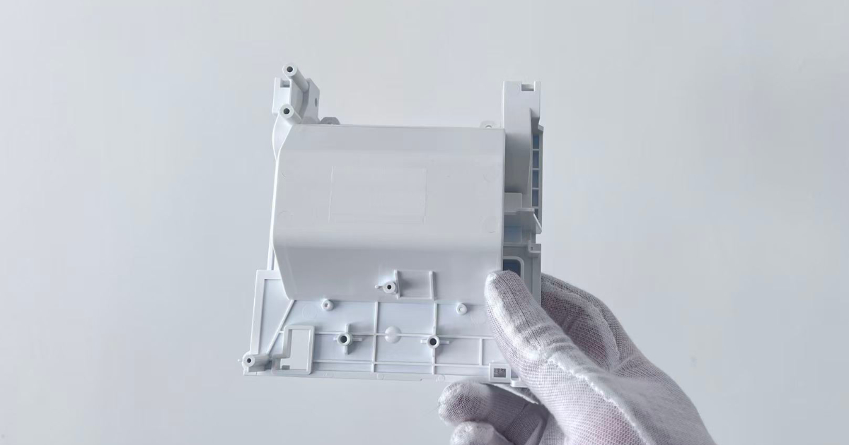
A point-of-sale equipment manufacturer developing a retail cash register system required a production mold for the internal receipt printer mounting bracket — a structural chassis component measuring 121 × 127 × 62 mm that locates and secures the thermal receipt printer mechanism within the cash register enclosure. At 80 grams with a nominal 2.5 mm wall thickness in PC+20% GF (glass fiber reinforced polycarbonate), the bracket must maintain dimensional accuracy across its mounting interfaces while withstanding the vibrational load of the printer mechanism during continuous receipt printing cycles.
The part geometry presented a classic DFM (Design for Manufacturing) challenge: the initial part design contained wall thickness variation from 2.5 mm at the thickest sections down to 1.0 mm at the thinnest — a 2.5:1 ratio that creates differential cooling rates, uneven shrinkage, and a high probability of warpage and dimensional instability in a glass-fiber-reinforced material where fiber orientation amplifies anisotropic shrinkage.
JBRplas performed a thermal analysis (Temperature Analysis) on the original part design to map the wall thickness distribution, identify stress concentration zones, and develop a targeted material reduction strategy. The optimized design achieved a uniform 1.5–2.3 mm wall thickness range — eliminating the 2.5:1 variation that drove the warpage risk — while maintaining all functional mounting interfaces and structural load paths.
The mold was executed as a three-plate cold-runner configuration with a pin gate (Φ1.0 mm × 0.1 mm recess), two mechanical slides for side-action features, and polished cavity surfaces. The three-plate design enables automatic runner separation at the mold parting line — the cold runner detaches from the part during mold opening without operator intervention, and the cold runner material is fully recyclable.
Part Specifications
| Parameter | Specification |
|---|---|
| Product | Retail cash register receipt printer mounting bracket |
| Dimensions | 121.0 × 127.0 × 62.0 mm |
| Weight | 80 g |
| Material | PC + 20% GF (glass fiber reinforced polycarbonate) |
| Shrinkage factor | 1.005 (0.5%) |
| Wall thickness (original) | 2.5 mm max / 2.3 mm avg / 1.0 mm min |
| Wall thickness (optimized) | 1.5–2.3 mm uniform distribution |
| Cavities | 1 |
| Mold type | Three-plate cold runner mold |
| Runner system | Cold runner |
| Gate type | Pin gate |
| Gate specification | Φ1.0 mm × 0.1 mm recess |
| Dimple specification | Φ3.0 mm × 0.5 mm deep |
| Flash control | ≤0.5 mm residual |
| Slides | 2 side actions |
| Press tonnage | 160T |
| Surface finish | Polished cavity (省光) |
| Application | Retail POS cash register, internal printer mounting |
Engineering Approach
DFM Thermal Analysis — Identifying the Root Cause of Warpage Risk
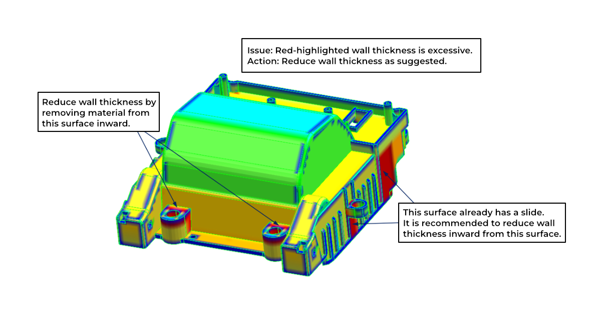
Before tooling began, JBRplas performed a thermal analysis of the original part geometry to map the wall thickness distribution across all sections of the bracket. The analysis revealed a significant wall thickness variation:
- Thickest section: 2.5 mm — concentrated in the top circular mounting boss area, the slide-side structural ribs, and the bottom flange zone
- Average thickness: 2.3 mm — across the main body walls
- Thinnest section: 1.0 mm — at transition zones between the main walls and thinner connecting webs
A thickness variation from 2.5 mm to 1.0 mm — a ratio of 2.5:1 — creates three interacting problems in a glass-fiber-reinforced material:
Differential cooling rate. The 2.5 mm sections cool substantially slower than the 1.0 mm sections. During the cooling phase, the thinner sections solidify and contract first, while the thicker sections remain molten and continue to shrink. This temporal mismatch in shrinkage generates internal residual stress — the thinner sections, already rigid, resist the contraction of the still-shrinking thicker sections, building stress that releases as warpage after ejection.
Fiber orientation disparity. In PC+20% GF, the glass fibers align with the flow direction during mold filling. In thick sections, the lower shear rate produces a more random fiber orientation; in thin sections, the higher shear rate produces strong flow-direction alignment. This creates a differential in directional shrinkage — the thin, highly-oriented sections shrink significantly more in the transverse-to-flow direction than the thick sections, amplifying the warpage tendency beyond what wall thickness variation alone would predict.
Sink mark formation at thickness transitions. The junction where a 2.5 mm section transitions to a 1.0 mm section represents a localized mass of material that cools more slowly than either adjacent wall. This creates a volumetric deficit (sink) that, on an internal bracket surface, affects dimensional accuracy at mounting interfaces.
Wall Thickness Optimization — Three-Face Material Reduction
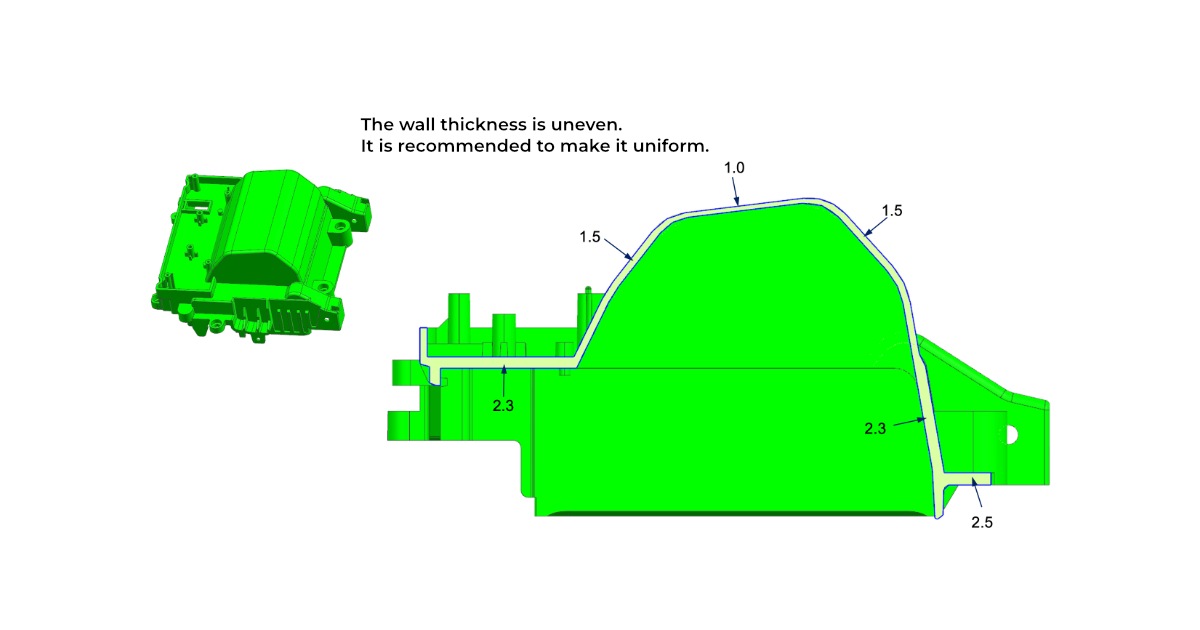
JBRplas proposed a targeted material reduction strategy on three specific faces of the bracket, reducing the 2.5 mm thick zones to achieve a uniform 1.5–2.3 mm distribution across the entire part:
Face 1 — Top Circular Area. The top circular boss and surrounding platform measured up to 2.5 mm — the single thickest section in the original design. JBRplas specified a unilateral material reduction of 0.5–1.0 mm from the designated face, transitioning the thickness smoothly from the boss root (where some structural mass is justified by the fastener load) outward to 1.5 mm at the periphery. The transition gradient ensures no abrupt thickness steps that would create a new stress concentration.
Face 2 — Slide-Side Structural Zone. The region adjacent to the two mechanical slides contained reinforcing ribs and mounting bosses that produced localized 2.5 mm sections. JBRplas reduced material from the inner face — accessible because the slide action already creates a side opening in the mold — taking the thickness down to approximately 2.0 mm. This reduction preserved the structural function of the slide-side features (the slides form undercut geometry that must remain dimensionally stable) while eliminating the excess mass that drove differential cooling.
Face 3 — Bottom Flange Area. The bottom mounting flange, designed to seat against the cash register chassis, measured up to 2.5 mm in localized zones. JBRplas reduced this to a uniform 1.5 mm — the minimum wall thickness in the optimized distribution. At 1.5 mm, the flange retains sufficient compressive strength for the mounting load (the bracket weighs 80 g and supports a thermal printer mechanism of approximately 200–300 g — the static load on the flange is under 4 N per mounting point), while the uniform thickness eliminates the localized hot spots that would otherwise produce sink marks at the flange-to-wall junction.
The result of the three-face reduction is a wall thickness distribution of 1.5–2.3 mm — a ratio of approximately 1.5:1, down from the original 2.5:1. This narrower thickness range produces more uniform cooling, reduced residual stress, and substantially lower warpage risk. The smooth thickness transitions — achieved through gradual reduction rather than stepped changes — prevent the stress concentration that would occur at an abrupt thickness step.
Shut-Off Insert Draft Optimization — Eliminating Flash at Four Locations
The bracket design incorporates four shut-off (枕位插穿) positions where core and cavity inserts meet to form through-holes, slots, or parting-line features. In the original design, these shut-off surfaces were designed with minimal or zero draft — producing a near-vertical interface between the two mold halves.
In a three-plate mold running PC+20% GF at 160T clamp force, a zero-draft shut-off surface creates two problems:
Flash formation. When the mold closes, the shut-off surfaces must mate with precision to prevent melt from entering the interface gap. With zero draft, any slight misalignment between core and cavity — from thermal expansion, press platen deflection, or insert wear — creates a gap at the shut-off that fills with melt, producing flash on the molded part.
Insert wear acceleration. A zero-draft shut-off means the mating surfaces slide against each other during every mold close and open cycle. The glass fiber content in PC+20% GF is abrasive — any flash that solidifies at the shut-off interface acts as a grinding compound during mold opening, accelerating insert wear and progressively enlarging the shut-off clearance over the mold’s service life.
JBRplas added a 3° draft angle per side at all four shut-off insert positions. The 3° draft provides three benefits:
- Self-aligning closure. The tapered interface guides the core and cavity inserts into alignment as the mold closes — the draft acts as a lead-in, compensating for minor misalignment and ensuring the shut-off faces mate cleanly before injection pressure is applied.
- Flash resistance. The angled interface creates a wedging effect under clamp force — the 160T clamp pressure drives the tapered faces together, closing any micro-gap at the shut-off and preventing melt penetration. The 3° angle is sufficient to create this wedging action without requiring excessive clamp force.
- Reduced wear. The draft angle means the mating surfaces do not rub against each other during mold opening — the core retracts along the draft direction, releasing cleanly from the cavity insert without grinding solidified flash residue against the shut-off faces.
Material Selection — Why PC+20% GF for an Internal Printer Bracket
The material selection of PC+20% GF for this internal structural bracket is driven by three functional requirements specific to a receipt printer mounting application:
Dimensional stability under thermal load. A thermal receipt printer operates at printing temperatures of 50–80°C at the print head — and in a cash register enclosure with limited ventilation, the ambient temperature around the bracket can reach 45–55°C during continuous operation. Standard ABS, with a heat deflection temperature (HDT) of approximately 85–95°C at 1.82 MPa, would be operating within 30–40°C of its softening point — too close for sustained dimensional stability. PC+20% GF delivers an HDT of approximately 135–145°C at 1.82 MPa, providing a margin exceeding 80°C above the maximum service temperature.
Stiffness for vibrational load. The receipt printer cycles continuously during printing — the paper feed motor, cutter mechanism, and print head carriage all generate vibration that transmits through the mounting points into the bracket. A material with insufficient stiffness would amplify this vibration, potentially affecting print quality through resonance or, over time, producing fatigue cracking at the mounting bosses. The 20% glass fiber reinforcement increases the flexural modulus from approximately 2,300 MPa (unfilled PC) to approximately 5,500–6,500 MPa — roughly 2.5× the stiffness of unfilled PC and approximately 3× that of standard ABS. This elevated modulus shifts the bracket’s natural frequency above the excitation frequencies of the printer mechanism, avoiding resonance in the operating range.
Creep resistance under sustained clamp load. The mounting screws that secure the bracket to the cash register chassis apply a sustained compressive load at the boss locations. Over the product’s service life — potentially 5–7 years of continuous retail operation — creep (time-dependent deformation under constant load) could loosen the mounting, producing rattling or misalignment. The glass fiber reinforcement in PC+20% GF significantly improves creep resistance compared to unfilled PC or ABS — the fibers act as load-bearing elements that resist the molecular chain movement responsible for creep deformation.
The trade-off of glass fiber reinforcement is increased melt viscosity and abrasive wear on the mold. The 20% GF loading raises the melt viscosity substantially — PC+20% GF requires higher injection pressure and a faster injection speed than unfilled PC to fill the cavity before the flow front freezes. The 160T press specified for this mold provides adequate injection pressure capacity for the 80 g shot weight through a pin gate in a single-cavity configuration.
Three-Plate Mold with Cold Runner — Design Rationale
The three-plate mold configuration was selected for this application based on three engineering considerations:
Pin gate positioning flexibility. A pin gate requires the gate to be positioned on the part surface — not at the parting line edge. In a two-plate mold, this would require a submarine gate or a direct sprue gate, neither of which provides the gate placement flexibility needed for this bracket geometry. The three-plate design separates the runner from the part at a second parting line (the stripper plate), allowing the pin gate to be positioned anywhere on the part surface for optimal fill. In this bracket, the pin gate is positioned on a non-functional internal surface where the Φ1.0 mm gate vestige — controlled by the 0.1 mm recess — does not interfere with assembly or function.
Automatic runner separation. During mold opening, the three-plate mold sequence opens the first parting line (between the runner plate and the stripper plate), stripping the cold runner away from the part. The runner remains attached to the sprue puller in the runner plate, while the part stays on the core. At the second parting line opening, the runner is ejected from the runner plate. The entire sequence is automatic — no operator is needed to cut or separate runners from parts, eliminating a secondary manual operation and its associated labor cost and cycle time variability.
Cold runner material recyclability. The cold runner system produces a solidified runner — the PC+20% GF material that fills the runner channels during injection. Unlike a hot runner system where the runner material remains molten, the cold runner solidifies and is ejected as a separate piece. This solidified runner is regrindable — it can be ground and blended back into virgin material at a controlled regrind ratio (typically 15–25% for glass-fiber-reinforced materials where fiber length degradation in regrind must be managed). The cold runner approach avoids the higher tooling cost and maintenance complexity of a hot runner system — appropriate for a single-cavity mold at 80 g shot weight where the runner-to-part weight ratio is manageable.
Pin Gate and Dimple Design
The pin gate specification — Φ1.0 mm × 0.1 mm recess — is sized for PC+20% GF in a single-cavity application:
Φ1.0 mm diameter provides sufficient flow area for the 80 g shot weight while maintaining a gate freeze time short enough that the gate seals before the holding pressure phase ends. A gate diameter below 0.8 mm would increase shear heating at the gate — a concern with glass-fiber-reinforced material where excessive shear can break fibers, reducing mechanical properties at the gate region. A diameter above 1.2 mm would extend the gate freeze time, reducing cycle time efficiency without a corresponding fill benefit at this shot weight.
0.1 mm recess creates a controlled gate vestige — the raised dimple on the part surface where the gate breaks. At 0.1 mm, the vestige is below the 0.5 mm flash control threshold and does not interfere with the bracket’s mounting function. The recess also creates a predetermined break point — the gate separates cleanly at the recess rather than tearing irregularly at the part surface.
The dimple specification — Φ3.0 mm × 0.5 mm deep — is positioned at the gate location to serve as a sink reservoir. As the 2.3 mm wall section around the gate cools and shrinks, the dimple (a localized thicker section at Φ3.0 mm) remains molten slightly longer, feeding material back into the shrinking gate region. This prevents a sink mark at the gate — a common cosmetic defect that, while not critical on an internal bracket, would indicate inconsistent packing and a potential weak point at the gate location.
Mold Design Details
| Parameter | Detail |
|---|---|
| Mold type | Three-plate injection mold |
| Cavities | 1-cavity |
| Mold steel | P20 (core & cavity inserts) |
| Runner system | Cold runner |
| Gate type | Pin gate, Φ1.0 mm × 0.1 mm recess |
| Gate location | Internal non-functional surface |
| Dimple | Φ3.0 mm × 0.5 mm deep at gate |
| Cooling | Water cooling lines |
| Ejection | Multi-point ejector pins on internal ribs |
| Side actions | 2 mechanical slides |
| Shut-off inserts | 4 locations, 3° draft per side |
| Surface finish | Polished cavity |
| Flash control | ≤0.5 mm |
| Mold life | 300,000 shots |
The two mechanical slides form the side-action undercuts on the bracket — features that cannot be released by the primary mold opening direction. In a three-plate mold, the slide actuation is integrated into the mold opening sequence: the slides retract during the first parting line opening before the part is stripped from the core, ensuring clean release of the undercut geometry without drag marks or deformation.
The polished cavity surface (省光) is specified for the internal bracket — while this is a non-cosmetic part, a polished surface reduces ejection friction, minimizes the adhesion of any outgassing residue from the PC material, and extends the interval between mold cleaning cycles.
Injection Molding Process
| Parameter | Value |
|---|---|
| Material | PC + 20% GF |
| Press tonnage | 160T |
| Barrel temperature | 280–300°C (zoned) |
| Mold temperature | 80–100°C |
| Injection pressure | 1,000–1,400 bar |
| Injection speed | Medium-high |
| Holding pressure | 40–60% of injection pressure |
| Holding time | 8–10 s |
| Cooling time | 18–22 s |
| Total cycle time | 40–48 s |
| Material drying | 120°C × 4 hours, moisture <0.02% |
The processing window for PC+20% GF is narrower and more demanding than unfilled PC. The glass fiber reinforcement raises the melt viscosity and reduces the melt flow index — the barrel temperature must be maintained at 280–300°C to achieve adequate melt fluidity for filling the cavity, approximately 20–30°C higher than unfilled PC processing temperatures. However, the upper limit is constrained by the thermal stability of the PC resin — above 310°C, molecular weight degradation accelerates, producing a measurable reduction in impact strength at the finished part.
Material drying is particularly critical for PC+20% GF. Polycarbonate is hygroscopic — it absorbs atmospheric moisture that, if not removed before processing, hydrolyzes the polymer chains at melt temperature, producing bubbles (splay), reducing molecular weight, and compromising mechanical properties. The 120°C × 4-hour drying cycle with a dew-point desiccant dryer reduces moisture content below 0.02% — the threshold above which hydrolytic degradation becomes measurable in PC. Glass fiber reinforcement does not reduce the drying requirement; if anything, the higher processing temperature makes moisture control more critical because hydrolysis reaction rates increase with temperature.
The 80–100°C mold temperature is essential for PC+20% GF surface quality and dimensional control. At mold temperatures below 70°C, the melt skin freezes too rapidly, producing a dull surface finish and increasing molded-in stress. At 80–100°C, the mold surface temperature allows the melt to replicate the polished cavity surface before the skin solidifies, while providing sufficient cooling rate for cycle time efficiency. The elevated mold temperature also reduces the cooling rate differential between thick and thin sections — directly supporting the wall thickness optimization strategy by producing more uniform shrinkage across the part.
Quality Control
Each production batch undergoes a structured inspection protocol:
- Dimensional inspection — CMM full-layout on first article and 1:200 sampling; overall dimensions verified against 121.0 ± 0.2 × 127.0 ± 0.2 × 62.0 ± 0.2 mm; mounting hole positions verified against ±0.15 mm
- Wall thickness verification — Ultrasonic thickness gauge measurement at 12 defined points across the three optimized faces on 1:50 samples; thickness within 1.5–2.3 mm range at all measured points
- Flash inspection — 100% visual inspection under 800 lux at shut-off locations and gate area; residual flash ≤0.5 mm; gate vestige ≤0.1 mm above surface
- Warpage measurement — Dial indicator sweep across mounting flange plane on 1:100 samples; flatness deviation <0.3 mm
- Shut-off integrity — Go/No-Go gauge check on all four shut-off hole/slot dimensions; 5 parts per shift
- Surface appearance — 100% visual inspection for sink marks, burn marks, splay, and gate quality on polished surfaces
- Weight consistency — Shot-to-shot weight variation <1.5%
- Assembly fit test — Functional assembly with mating printer mechanism and cash register chassis on 1:200 samples; all mounting points engage without interference
Results
| Metric | Target | Achieved |
|---|---|---|
| Overall dimensional tolerance | ±0.2 mm | Cpk = 1.42 |
| Mounting hole position | ±0.15 mm | Cpk = 1.48 |
| Wall thickness uniformity | 1.5–2.3 mm | 1.6–2.2 mm |
| Flatness (mounting flange) | <0.3 mm | 0.21 mm average |
| Flash at shut-off locations | ≤0.5 mm | ≤0.3 mm |
| Gate vestige | ≤0.1 mm | ≤0.08 mm |
| Surface finish | No sink marks, no splay | ✅ Pass |
| Shot-to-shot weight variation | <1.5% | 0.9% |
| Assembly fit | All points engage | ✅ Pass, zero interference |
| Cycle time | ≤50 s | 44 s |
The three-face wall thickness optimization proved effective in eliminating the warpage tendency identified in the original thermal analysis. The optimized 1.6–2.2 mm thickness distribution — a ratio of approximately 1.4:1, down from the original 2.5:1 — produced flatness deviation of 0.21 mm across the mounting flange, well within the 0.3 mm target. The smooth thickness transitions between the reduced and retained sections prevented any new stress concentration from developing at the transition zones.
The 3° shut-off draft at the four insert positions eliminated the flash risk that a zero-draft design would have presented with PC+20% GF. All four shut-off locations produced flash ≤0.3 mm — below the 0.5 mm threshold — across the full production run. The draft also delivered the expected insert wear reduction: after 50,000 shots, the shut-off inserts showed no measurable clearance increase.
The three-plate cold-runner configuration with automatic runner separation eliminated the secondary manual degating operation, reducing per-part labor content. The cold runner material — PC+20% GF — was reground and blended at 20% regrind ratio without measurable impact on mechanical properties or dimensional consistency, as confirmed by the 0.9% shot-to-shot weight variation and stable Cpk values across the production run.
This case study demonstrates JBRplas’s DFM capability for wall thickness optimization — including thermal analysis-driven material reduction across three faces, shut-off insert draft engineering for flash elimination in glass-fiber-reinforced materials, and three-plate cold-runner pin-gate mold design with automatic runner separation for efficient single-cavity production.