Project Overview
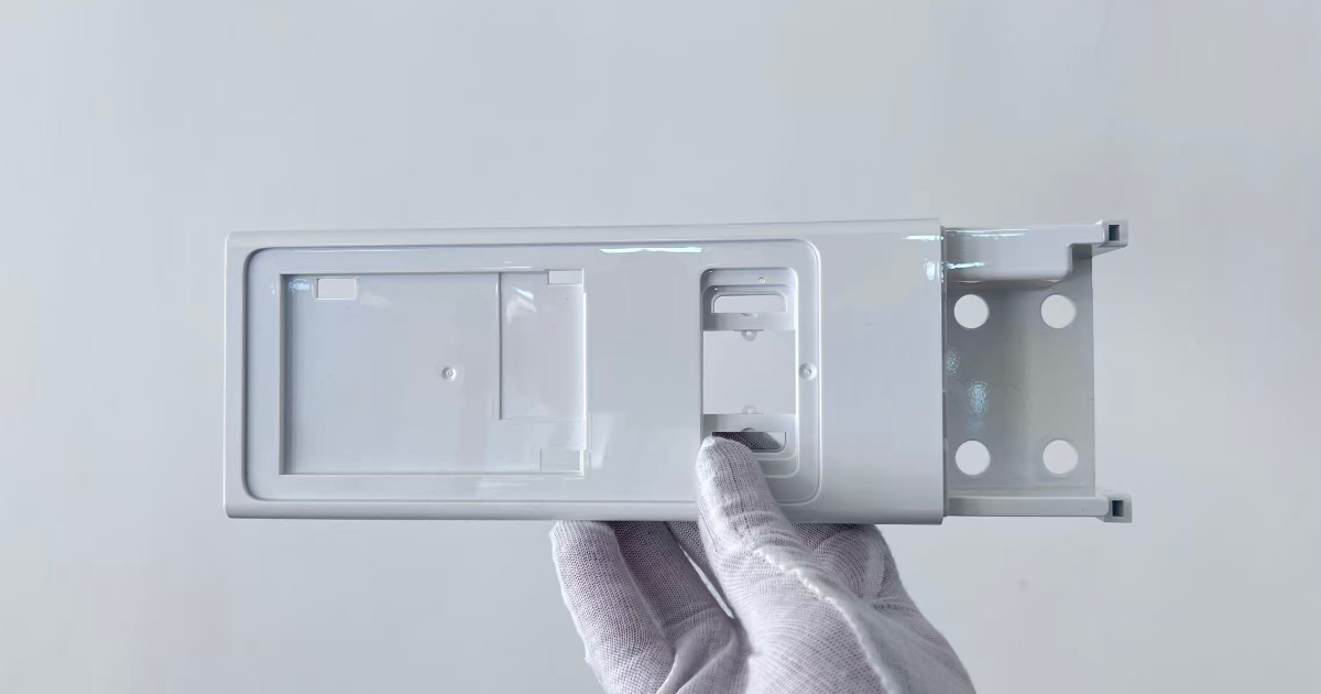
A point-of-sale equipment manufacturer developing a retail cash register system required a production mold for the monitor support bracket — an elongated structural housing measuring 80 × 245 × 30 mm that serves as the mechanical interface between the cash register base and the customer-facing display panel. At 65 grams in PC+ABS, the bracket must support the weight of a 10–15 inch LCD monitor while maintaining flatness across a 245 mm span — a length-to-height aspect ratio of approximately 8:1 that makes flatness control the defining engineering challenge of this part.
Unlike a compact enclosure where stiffness derives naturally from box geometry, a long-span support bracket resists bending primarily through material modulus and rib architecture. At 245 mm in length with only 30 mm of section height, the bracket’s second moment of area is inherently limited — the geometry itself provides minimal resistance to deflection along the long axis. The injection molding process compounds this challenge: differential cooling along the 245 mm length generates residual stress that, if not managed through wall thickness uniformity and rib design, releases as warpage after ejection.
The bracket also incorporates mounting bosses for the display hinge mechanism, threaded insert receiving holes, snap-fit retention features for the cosmetic cover, and an exterior surface that is visible to the customer in the assembled cash register. The visible surface means that sink marks, weld lines, and flow marks are cosmetic defects — the structural and aesthetic requirements converge in a single part.
Part Specifications
| Parameter | Specification |
|---|---|
| Product | Retail cash register monitor support bracket |
| Dimensions | 80.0 × 245.0 × 30.0 mm |
| Weight | 65 g |
| Material | PC+ABS (engineering grade) |
| Cavities | 1 |
| Mold type | Two-plate injection mold |
| Runner system | Cold runner |
| Application | POS cash register display stand |
Engineering Approach
The Long-Span Flatness Problem
The defining characteristic of this bracket is its elongation. At 245 mm in length with a 30 mm section height, the part has a length-to-height ratio of approximately 8:1 — meaning the bracket is eight times longer than it is tall. In this geometric regime, flatness is not a given; it must be engineered.
Three factors interact to determine the post-molding flatness of a long-span PC+ABS part:
Cooling rate differential along the flow path. The melt enters the cavity at the gate and flows 245 mm to the far end. The material at the gate end has been in contact with the mold steel for significantly longer than the material at the flow front — the gate-end material begins cooling while the far-end material is still being injected. This longitudinal temperature gradient produces a corresponding gradient in shrinkage: the gate end shrinks more (having cooled from a higher average temperature) while the far end shrinks less. The result is a bending moment that curves the part along its long axis.
Frozen-in orientation stress. The 245 mm flow length through an 80 mm wide, thin-wall cross-section produces high shear stress in the melt as it flows through the narrow cavity. PC+ABS, with its two-phase polymer morphology, develops molecular orientation along the flow direction. This orientation relaxes during cooling — but the relaxation is incomplete, leaving residual stress frozen into the solidified part. When the part is ejected and the mold constraint is removed, this residual stress redistributes, producing distortion along the flow direction.
Pack pressure decay with distance. The holding pressure applied at the gate must transmit through 245 mm of progressively solidifying material to pack the far end of the cavity. As the material cools and the flow channel narrows, the pressure at the far end decays relative to the gate pressure. This longitudinal pressure gradient produces a density gradient — the gate end is better packed and denser than the far end — which translates to a differential shrinkage that further contributes to long-axis warpage.
Gating Strategy for Elongated Geometry
The gate position for an elongated part determines the flow length, the orientation of the melt front, and the location of the weld line if the flow splits around a core feature. For this 245 mm bracket, the gate was positioned to minimize the flow length — placed near the geometric center of the part rather than at one end, reducing the maximum flow distance from 245 mm (end-gated) to approximately 120 mm (center-gated).
A center gate provides two benefits for flatness:
Reduced flow length. The 120 mm flow length from center to each end is approximately half the 245 mm that an end-gate would require. Shorter flow length means less pressure drop, more uniform packing, and a smaller longitudinal temperature differential — all directly reducing the driving forces for warpage.
Symmetric filling pattern. The melt front propagates outward from the center in both directions simultaneously, producing a symmetric flow pattern. Symmetric flow produces symmetric stress distribution — and while symmetric stress still produces some distortion, symmetric distortion is predictable and correctable through mold compensation, whereas asymmetric distortion from an end-gate is harder to predict and harder to correct.
Rib Architecture — Creating Section Height Where It Counts
With a base section of only 30 mm, the bracket’s inherent bending stiffness is limited. The second moment of area for a rectangular cross-section scales with the cube of height — doubling the effective section height increases bending stiffness by a factor of eight. The rib design on the internal (non-visible) face of the bracket achieves this by adding vertical ribs that, together with the base wall, create a T-section with an effective height substantially greater than the 30 mm base dimension.
The ribs are designed following plastic part design principles:
- Rib thickness at 0.5–0.6× the nominal wall avoids sink marks on the visible exterior surface. The rib root cools at approximately the same rate as the adjacent wall, preventing the localized shrinkage differential that would telegraph through to the cosmetic face.
- Rib orientation parallel to the 245 mm long axis places the stiffening material exactly where it resists the primary bending direction. Transverse ribs, while useful for torsional stiffness, contribute less to long-axis bending resistance per gram of material.
- Rib depth maximized within ejection constraints — the ribs extend as far into the interior cavity as the draft angle and ejection stroke allow, maximizing the effective section height and the resulting bending stiffness.
Material Selection — Why PC+ABS for a Long-Span Cosmetic Structural Part
The material requirements for this bracket span structural, cosmetic, and processability domains:
Stiffness for deflection resistance. The long span demands a material with sufficient flexural modulus to limit deflection under the cantilevered weight of the display. PC+ABS delivers a flexural modulus of approximately 2,300–2,500 MPa — higher than standard ABS (1,800–2,200 MPa) and approaching that of unfilled PC (2,300–2,400 MPa). This modulus, combined with the rib-reinforced cross-section, keeps the deflection under load within the dimensional tolerance required for consistent display alignment.
Impact resistance at mounting points. The bracket’s mounting bosses — where the display hinge mechanism attaches — are localized stress concentrations that experience both static load and occasional impact (customer adjustment of the display angle, accidental knocks during cleaning). PC+ABS provides notched Izod impact strength in the 35–50 kJ/m² range, offering a meaningful margin above standard ABS (20–30 kJ/m²) at the boss locations where stress concentrates.
Flowability for a 245 mm flow length. Compared to PC or PC+GF, PC+ABS offers improved melt flow — the ABS component reduces the melt viscosity relative to unfilled PC, allowing the material to fill the 245 mm cavity at lower injection pressure and with less shear heating. This is particularly important for an elongated part where the flow length places a premium on material fluidity.
Cosmetic surface quality. The visible exterior surface of the bracket must be free of flow marks, sink marks, and surface defects. PC+ABS, with its balanced viscosity and good mold surface replication, produces a cosmetically clean surface from a polished cavity without requiring secondary finishing — an advantage over glass-filled materials where exposed fibers at the surface create a matte, textured appearance that may not meet the cosmetic requirement.
Mold Design — Cold Runner, Single Cavity
The single-cavity configuration is driven by the part size and production volume. At 245 × 80 mm, a single cavity already occupies a mold base in the 400–500 mm range. A two-cavity layout would require a press capacity exceeding 300 tonnes — disproportionate to the 65 g shot weight and the client’s mid-volume production requirement.
The cold runner system delivers the melt from the sprue bushing to the center gate through a short, direct runner channel. For a single-cavity mold at 65 g shot weight, a cold runner provides the simplest, most cost-effective feeding solution — the runner weight is a small fraction of the part weight, and the cold runner tooling cost is significantly lower than an equivalent hot runner system.
The mold incorporates water cooling lines positioned along the 245 mm length, with independent circuits for the core and cavity sides. The cooling design aims to produce a uniform cooling rate along the flow path — the line spacing and distance from the cavity surface are designed to extract heat at a consistent rate from gate to flow front, minimizing the longitudinal temperature differential that drives warpage.
Mold Design Details
| Parameter | Detail |
|---|---|
| Mold type | Two-plate injection mold |
| Cavities | 1-cavity |
| Mold steel | P20 (core & cavity) |
| Runner system | Cold runner |
| Gate type | Center gate on internal face |
| Cooling | Water cooling, circuits along 245 mm axis |
| Ejection | Multi-point ejector pins on internal ribs and perimeter |
| Surface finish | Polished cavity (visible exterior face) |
| Mold life | 300,000 shots |
Injection Molding Process
| Parameter | Value |
|---|---|
| Material | PC+ABS, engineering grade |
| Barrel temperature | 240–260°C (zoned) |
| Mold temperature | 60–80°C |
| Injection pressure | 800–1,100 bar |
| Injection speed | Medium |
| Holding pressure | 35–50% of injection pressure |
| Holding time | 8–10 s |
| Cooling time | 15–20 s |
| Total cycle time | 38–45 s |
| Material drying | 80°C × 4 hours, moisture <0.02% |
The 240–260°C barrel temperature range balances the processing requirements of both the PC and ABS components. PC processes optimally at 270–300°C, while ABS processes at 220–250°C. Running at 240–260°C — in the overlap window — ensures adequate melt fluidity from the PC fraction without thermally degrading the ABS fraction (which begins to degrade above 260°C with prolonged residence time).
The 60–80°C mold temperature is set at the moderate level appropriate for PC+ABS cosmetic parts. Below 50°C, the melt skin freezes too rapidly, producing surface defects (flow marks, dull finish) on the visible face. Above 90°C, the extended cooling time increases cycle time without a corresponding cosmetic improvement for this wall thickness.
Material drying at 80°C for 4 hours addresses the PC component’s hygroscopic nature. The ABS component also absorbs moisture, though to a lesser degree. The combined material requires the same drying discipline as unfilled PC — moisture content below 0.02% is the threshold for preventing hydrolytic degradation and surface splay at processing temperature.
Quality Control
- Dimensional inspection — CMM full-layout on first article and 1:200 sampling; overall dimensions verified against 80.0 ± 0.2 × 245.0 ± 0.3 × 30.0 ± 0.2 mm
- Flatness measurement — Dial indicator sweep across the 245 mm mounting face on 1:100 samples; flatness deviation <0.4 mm across the full length
- Mounting boss position — CMM verification of boss center positions against ±0.15 mm
- Surface appearance — 100% visual inspection on visible exterior face for sink marks, flow lines, and surface defects
- Threaded insert retention — Pull-out force test on 1:200 samples; insert retention force above specified minimum
- Load deflection — Static load test with 3 kg distributed weight simulating display assembly; deflection <0.5 mm at free end
- Weight consistency — Shot-to-shot weight variation <1.5%
- Assembly fit — Functional assembly with mating display hinge and cosmetic cover; all mounting points engage without interference
Results
| Metric | Target | Achieved |
|---|---|---|
| Overall dimensional tolerance (length) | ±0.3 mm | Cpk = 1.40 |
| Mounting boss position | ±0.15 mm | Cpk = 1.45 |
| Flatness (245 mm span) | <0.4 mm | 0.28 mm average |
| Surface finish (visible face) | No sink marks, no flow lines | ✅ Pass |
| Static load deflection (3 kg) | <0.5 mm | 0.31 mm |
| Shot-to-shot weight variation | <1.5% | 1.0% |
| Assembly fit | All points engage | ✅ Pass, zero interference |
| Cycle time | ≤48 s | 42 s |
The center-gate strategy combined with rib reinforcement along the 245 mm axis proved effective in controlling long-span warpage. The 0.28 mm flatness deviation across the full 245 mm length — equivalent to a flatness error of approximately 0.1% of span — demonstrates that the cooling design, gate position, and rib architecture worked together to manage the longitudinal stress that drives distortion in elongated parts.
The PC+ABS material selection delivered the required combination of structural stiffness, cosmetic surface quality, and processability. The 0.31 mm deflection under 3 kg static load confirms that the rib-reinforced cross-section provides adequate bending stiffness for the display support application without requiring a heavier, bulkier section that would increase material cost and cycle time.
The 42-second cycle time on a single-cavity mold provides production throughput of approximately 85 parts per hour — sufficient for the client’s production schedule with capacity for demand variation across product generations.
This case study demonstrates JBRplas’s capability for long-span structural injection molding — including PC+ABS material selection for stiffness-cosmetic-processability balance, center-gate strategy for elongated geometry flatness control, rib architecture for bending stiffness with sink-mark prevention, and dimensional control across an 8:1 aspect ratio structural housing.