Project Overview
An audio equipment manufacturer developing a portable wireless microphone for live streaming and content creation required a production mold for the device housing — a compact injection-molded shell measuring 25 × 52 × 9 mm with a uniform 2.0 mm wall thickness. At just 2.9 grams per piece, the housing encloses the microphone capsule, PCB, battery, and wireless antenna in a handheld form factor that must survive frequent handling, cable strain, and the occasional drop from desk height.
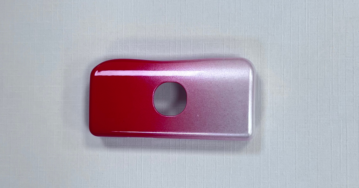
The visual requirement was unusually demanding for an audio accessory: a red-to-purple gradient high-gloss finish that transitions smoothly across the housing surface. Unlike a solid color, a gradient demands precise spray control — the transition zone must be seamless, with no visible banding, color steps, or overspray at the boundary. Any surface defect beneath the paint — a sink mark, a flow line, a subtle knit line — becomes immediately visible through the high-gloss clear coat.
With 16 precision holes distributed across the housing for PCB mounting, component alignment, microphone pickup, and assembly guidance, the mold required a multi-cavity approach with exacting pin placement and hole-to-hole positional accuracy.
Part Specifications
| Parameter | Specification |
|---|---|
| Product | Portable microphone housing |
| Dimensions | 25.0 × 52.0 × 9.0 mm |
| Weight | 2.9 g |
| Material | PC/ABS (engineering grade) |
| Wall thickness | 2.0 mm nominal |
| Hole count | 16 holes (4 configurations) |
| Surface finish | Red-purple gradient high-gloss spray painting |
| Critical tolerance | ±0.15 mm |
| General tolerance | ±0.3 mm |
Engineering Approach
Material Selection — PC/ABS vs. PMMA
The client evaluated two materials for the housing: PC/ABS blend and PMMA (acrylic). Each offered a distinct set of trade-offs for this application.
PC/ABS was ultimately selected for three reasons:
Impact resistance. A portable microphone housing endures frequent handling, cable tugging, and occasional drops. PC/ABS delivers notched Izod impact strength of 45–55 kJ/m² — roughly 3× that of standard PMMA. A 1.2 m free-fall drop test onto concrete, required by the client’s quality specification, is well within the capability of a PC/ABS housing at 2 mm wall thickness.
Paint adhesion without primer. The polycarbonate fraction in PC/ABS provides polar surface groups that bond directly with PU-based primers, eliminating the need for a separate adhesion promoter or flame treatment that PMMA typically requires before painting.
Dimensional stability across 16 cavities. PC/ABS exhibits predictable, well-characterized shrinkage behavior that is easier to compensate for across a multi-cavity layout than PMMA, which is more sensitive to mold temperature variation and can produce cavity-to-cavity dimensional drift.
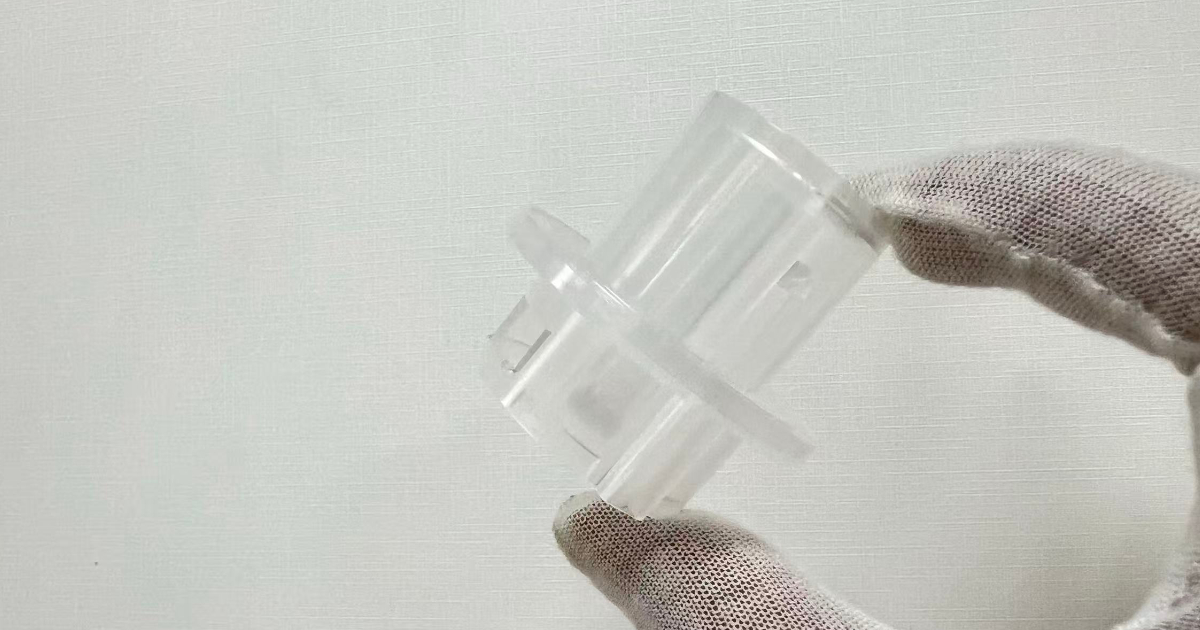
PMMA was considered for its superior optical clarity and surface hardness, but the application did not require transparency (the housing is fully painted), and the impact disadvantage was decisive. For applications where transparency or exceptional scratch resistance is required — such as a visible microphone grille or LED light pipe integrated into the housing — PMMA remains a viable alternative.
16-Hole Precision Layout
The housing incorporates 16 holes in four functional configurations, each with distinct positional tolerance requirements:
| Hole Type | Qty | Diameter | Function | Position Tolerance |
|---|---|---|---|---|
| PCB mounting | 8 | Φ3.5 mm | PCB screw fixation | ±0.15 mm |
| Component alignment | 4 | Φ2.0 mm | Internal component positioning | ±0.20 mm |
| Microphone pickup | 2 | Φ4.0 mm | Acoustic port for mic capsule | ±0.20 mm |
| Assembly guide | 2 | Φ2.5 mm | Housing half alignment posts | ±0.15 mm |
The 8 PCB mounting holes carry the tightest tolerance — ±0.15 mm — because the PCB is a rigid substrate that must align simultaneously across all 8 screw positions. A single hole off by 0.2 mm creates assembly interference that can crack the PCB during screw insertion.
The two microphone pickup holes require additional process control: the hole edge must be free of flash, burrs, or paint bridging that would obstruct the acoustic path. A 0.1 mm paint bridge across a Φ4.0 mm acoustic port reduces the effective open area by up to 10% and introduces audible frequency response alteration.
Hole-to-hole positional accuracy across the 16-cavity layout was achieved through precision-machined core pins with hardened steel inserts at each hole location, rather than relying on post-molding drilling. Molded-in holes eliminate a secondary operation and ensure consistent positional accuracy across production volumes.
Gradient Spray Painting Process
The red-purple gradient finish is the defining visual feature of this housing. Unlike a uniform color coat, a gradient requires two colors applied in a controlled transition zone where one color fades into the other without a visible boundary.
The production-scale spray painting process was sequenced as follows:
| Step | Process | Specification |
|---|---|---|
| 1 | Ultrasonic cleaning | Remove mold release residue and particulate |
| 2 | Drying | 60–80°C forced air, 10–15 min |
| 3 | Primer coat | PU primer, 15–20 µm DFT |
| 4 | Base color (red) | Applied to lower 60% of housing surface |
| 5 | Transition color (purple) | Applied to upper 40%, overlapping 15–20 mm transition zone |
| 6 | Clear coat | Transparent protective lacquer, 10–15 µm |
| 7 | Curing | 60°C oven, 30 min |
The gradient transition zone — a 15–20 mm band where red fades into purple — is the most process-sensitive step. The spray gun traverse speed, atomization pressure, and nozzle-to-part distance must be identical for both colors. The purple coat is applied while the red base is still tacky (flash-off time: 60–90 seconds at ambient), allowing the two colors to blend at the molecular interface rather than forming a sharp demarcation line.
Color consistency across production batches is verified with a spectrophotometer, with a maximum allowable color deviation of ΔE ≤ 1.5 in the transition zone. This is tighter than the ΔE ≤ 2.0 typical for solid-color consumer electronics, reflecting the visibility of even minor color shifts in a gradient.
Paint Quality Specifications
| Parameter | Specification | Test Method |
|---|---|---|
| Total film thickness | 35–45 µm | Eddy current gauge |
| Gloss level | ≥85 GU at 60° | Gloss meter |
| Adhesion | ≥Grade 3 | Cross-hatch tape test (ISO 2409) |
| Scratch resistance | No visible mark at 500 g | Pencil hardness / loaded stylus |
| Color deviation | ΔE ≤ 1.5 | Spectrophotometer |
The 35–45 µm total film thickness — primer + color coats + clear — is sufficient to produce a deep, wet-looking gloss without being so thick that it chips at the hole edges during assembly. Edges around the 16 holes are the highest-risk areas for paint delamination, and the 15–20 µm primer layer is specifically formulated to provide edge coverage on small-diameter holes without bridging or filling.
Mold Design and Cooling Strategy
A 16-cavity layout was selected to match the projected annual volume while maintaining a practical mold size for the client’s 200-ton injection molding machine. The cavities were arranged in a 4 × 4 matrix with a naturally balanced runner system feeding each quadrant.
At 2.0 mm nominal wall, the housing is thin enough that cooling uniformity across all 16 cavities is the dominant factor in dimensional consistency. A分流式 (split-flow) cooling circuit design ensures that coolant reaches every cavity at the same inlet temperature and flow rate. The cavity side is maintained 5°C cooler than the core side to bias shrinkage toward the non-cosmetic inner surface, keeping the visible exterior surfaces dimensionally stable.
The 1.5°–2.5° draft angle on vertical surfaces — combined with 8 small-diameter ejector pins distributed around the perimeter — achieves clean part release with an ejection force of 15–25 N per cavity. This low ejection force minimizes stress whitening, which is critical because any polymer stress concentration at an ejector pin location will telegraph through the gradient paint as a localized gloss variation.
Mold Design Details
| Parameter | Detail |
|---|---|
| Mold type | Two-plate injection mold |
| Cavities | 16 cavities (4 × 4 matrix) |
| Mold steel | P20 (core & cavity) |
| Runner system | Naturally balanced, split-flow |
| Cooling | Split-flow water cooling, cavity side biased 5°C cooler |
| Ejection | 8 perimeter ejector pins per cavity |
| Gate type | Edge gate on non-cosmetic surface |
| Core pins | Hardened steel inserts at all 16 hole positions |
| Draft angle | 1.5°–2.5° |
| Mold life | 500,000 shots |
Injection Molding Process
| Parameter | Value |
|---|---|
| Material | PC/ABS, engineering grade |
| Barrel temperature | 220–240°C (zoned heating) |
| Mold temperature | 50–60°C |
| Injection pressure | 80–120 MPa |
| Holding pressure | 60–80 MPa |
| Holding time | 3–5 s |
| Cooling time | 25–30 s |
| Total cycle time | 45–55 s |
| Material drying | 80°C × 4 hours, moisture <0.02% |
The barrel temperature of 220–240°C was selected for the PC/ABS grade used — slightly narrower than the 220–250°C range typical for general-purpose PC/ABS, reflecting the need for tighter thermal control when filling 16 thin-walled cavities simultaneously. The lower mold temperature of 50–60°C (compared to 70–80°C for thicker PC/ABS parts) accelerates skin formation and reduces cycle time for the 2 mm wall, while still allowing adequate cavity filling before the flow front freezes.
The 45–55 second total cycle time — including 25–30 seconds of cooling — was validated through mold flow analysis and confirmed at T1 sampling. At 16 parts per cycle, this yields approximately 1,050–1,280 parts per hour, supporting an annual production capacity exceeding 3 million units on a single mold.
Quality Control
Each production batch undergoes a structured inspection protocol:
- Dimensional inspection — CMM sampling at 1:100 frequency; all 16 hole positions verified against ±0.15 mm (PCB mounting and guide holes) or ±0.20 mm (alignment and pickup holes)
- Hole quality — 100% visual inspection of microphone pickup holes under 10× magnification for flash, burrs, or paint bridging
- Surface appearance — 100% visual inspection under 800 lux for gradient consistency, color banding, paint defects, and gloss uniformity
- Paint adhesion — Cross-hatch tape test per ISO 2409, adhesion ≥Grade 3 on all surfaces including hole edges
- Color measurement — Spectrophotometer verification of gradient transition zone, ΔE ≤ 1.5
- Scratch resistance — 500 g loaded stylus test on painted surface, no visible mark
- Drop test — 1.2 m free fall onto concrete, 6 orientations; no cracking or paint delamination
- Oil resistance — 48-hour immersion in mineral oil at 23°C; no dimensional change, no paint softening
- Weight consistency — Cavity-to-cavity weight variation <2.0%, verified per quality control protocol
Results
| Metric | Target | Achieved |
|---|---|---|
| Cavity weight variation (16 cavities) | <2.0% | 1.4% |
| Critical dimension tolerance | ±0.15 mm | Cpk = 1.48 |
| Hole positional accuracy | ±0.20 mm | Cpk = 1.62 |
| Surface gloss level | ≥85 GU at 60° | 86–91 GU |
| Gradient color deviation | ΔE ≤ 1.5 | ΔE = 0.8–1.3 |
| Paint adhesion (cross-hatch) | ≥Grade 3 | Grade 4 (no delamination at hole edges) |
| Drop test (1.2 m) | No crack, no paint damage | ✅ Pass, all orientations |
| Oil resistance (48 h) | No deformation or softening | ✅ Pass |
| Cycle time | ≤55 s | 48 s average |
| Per-part cost (incl. finishing) | ≤¥3.50 | ¥3.20 |
The 16-cavity mold entered stable production and has consistently delivered the gradient finish quality required for a consumer-facing audio product. The split-flow cooling design maintained cavity-to-cavity weight consistency within 1.4% across all 16 cavities — tighter than the 2.0% specification and notably strong for a 16-cavity layout where thermal variation typically compounds across the larger mold footprint.
The gradient spray painting process, validated through spectrophotometer measurements at 1:500 sampling frequency, maintained ΔE ≤ 1.3 across all production batches — well within the ≤1.5 specification and approaching the consistency of single-color consumer electronics finishes. The per-part cost of ¥3.20, including material, injection molding, 4-step spray painting, and quality inspection, met the cost target for a mid-range consumer audio product.
This case study demonstrates JBRplas’s capability for precision multi-cavity consumer electronics components — including 16-cavity balanced tooling with molded-in hole arrays, PC/ABS material selection for impact-critical audio devices, multi-step gradient spray painting, and integrated quality control for high-volume production.