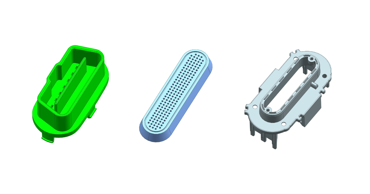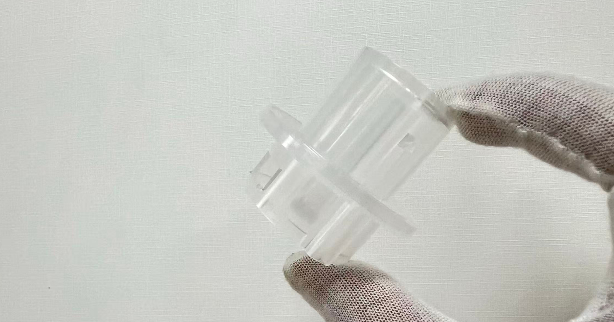
Project Overview
This project covered the DFM analysis and injection mold design of a plastic connector — a Ø52.48 × 47.86 mm body molded in PP-PR350. The part carries a flange, a side window and two square holes that cannot be released along the primary mold opening direction, and the customer’s 3D data modeled several cavity surfaces at 0° draft.
JBRplas reviewed the part geometry, mold opening direction, parting line, gating system, slider mechanisms, ejection structure and draft angles before any steel was cut. The review returned documented product modifications and a mold concept built around them: a 2-cavity Hasco-standard tool with H13 cavity and core, hot runner gating and dedicated slider and ejection structures.
Part Specifications
| Parameter | Specification |
|---|---|
| Product | Plastic connector |
| Material | PP-PR350 |
| Product dimensions | Ø52.48 × 47.86 mm |
| Mold configuration | 2 cavities |
| Mold base | Hasco standard |
| Mold steel | H13 / 420 SS |
| Mold size | 300 × 350 × 440 mm |
| Injection machine | 120 T |
| Mold weight | 380 kg |
| Target mold life | 1,000,000 shots |
DFM Findings: Features That Would Not Demold
The review concentrated on the areas where the part as drawn would have fought the mold. Each finding was documented with a markup drawing and a specific modification for customer approval.
Zero-Draft Cavity Surfaces
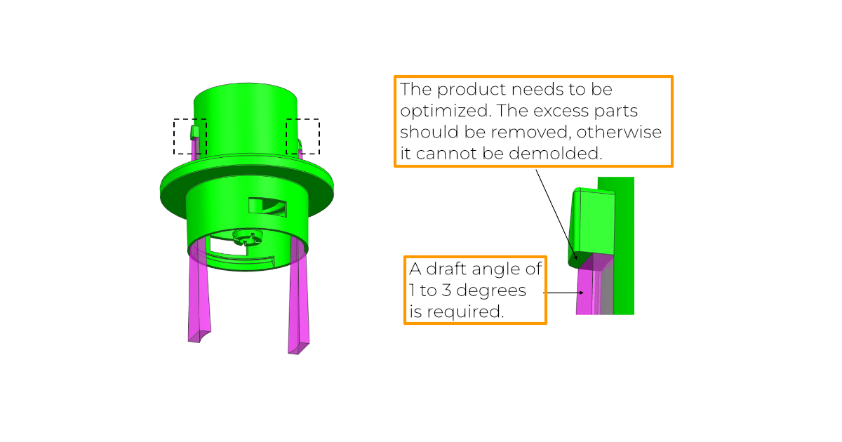
The DFM analysis identified vertical surfaces modeled at a 0° draft angle. A vertical wall can only release if the plastic shrinks away from the steel as it cools; at 0°, the surface instead drags against the cavity, scuffs the part and can hold it on the core during ejection. JBRplas recommended modifying the product geometry to introduce a 1°–3° draft angle and documented the affected surfaces in the DFM markup.
Two Square Holes on the Slider Direction
Two square holes in the connector must be formed by slides, and the holes themselves need draft along the slider movement direction — without it, the slide insert cannot withdraw cleanly from the hole. JBRplas recommended a 3° draft angle on both features and proposed the corresponding product design change.
Excess Material Interfering with Demolding
The DFM markup also identified excess material in the part geometry that would block demolding. The recommendation was to remove it from the product design before tooling — a change that costs nothing at the data stage and would have required re-cutting steel later.
Slider and Insert Design
The square holes are formed by slider mechanisms that pull away from the part before ejection. The mold concept pairs a slider block — with its travel direction defined in the concept drawing — with a slide insert that forms the square-hole features, so the slider can be serviced or replaced without touching the cavity block.
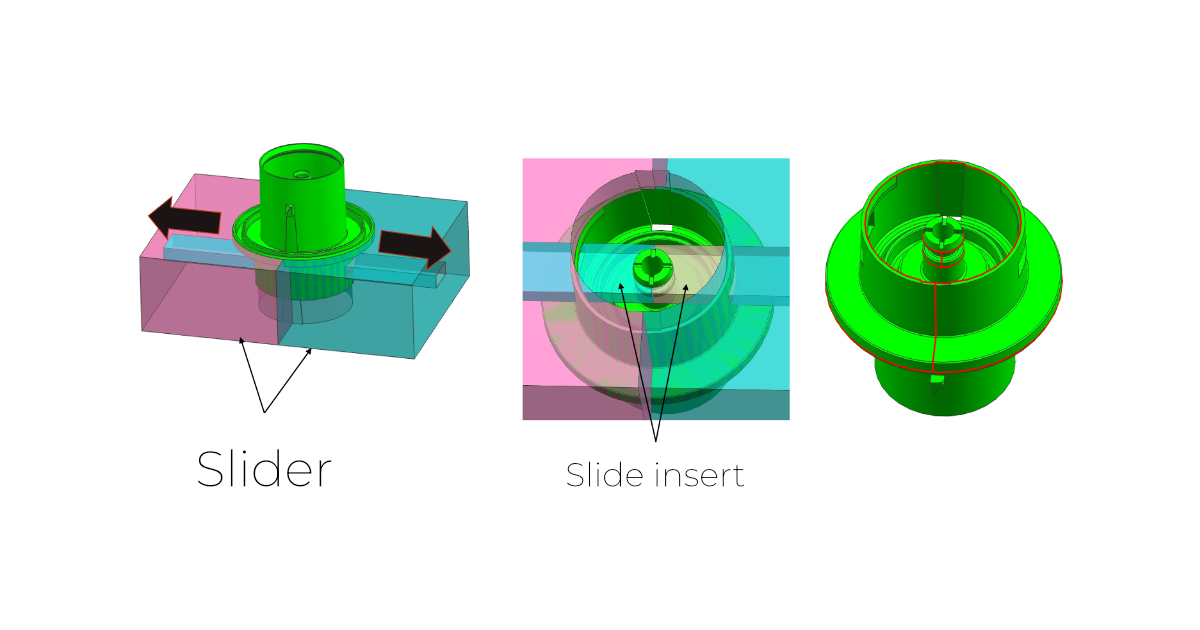
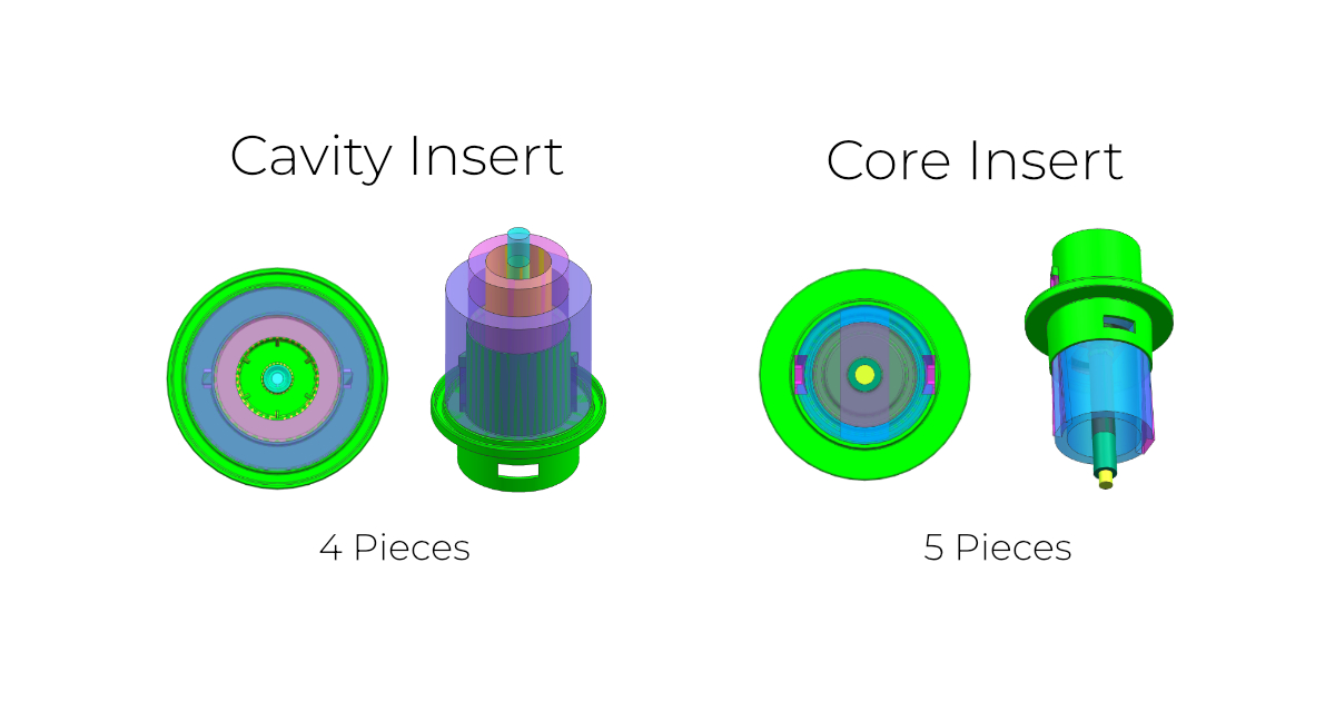
The cavity and core are built as modular insert assemblies rather than cutting the features directly into the blocks. The DFM design identifies four movable cavity inserts and five core inserts, so the features carrying the slider interfaces and the part’s internal geometry can be replaced or re-cut without reworking the mold base — the same modular logic documented in our family mold project.
Hot Runner, Gating and Ejection
The proposed design uses a hot runner system with one hot nozzle feeding a pin-point gate. The specified gate diameter is 2 mm, with an additional 1.2 mm pin-point gate dimension indicated in the DFM proposal. A pin-point gate leaves a small, clean gate mark that requires no finishing on a technical part like this connector — the reasoning behind gate type selection is covered in our gate design guide, and the runner decision trade-offs in the hot runner vs cold runner comparison.
For ejection, the proposed structure combines an ejector block and an ejector sleeve. A sleeve pushes the part off the core around its full circumference rather than at localized points, which suits the connector’s cylindrical body — the general principles are covered in our ejector system design guide.
Engineering Solutions Summary
| Identified issue | JBRplas recommendation |
|---|---|
| Zero-draft cavity surfaces | Add 1°–3° draft angles |
| Excess material interfering with demolding | Remove the identified excess material from the product design |
| Two square holes along the slider direction | Add 3° draft angles |
| Complex connector geometry | Use dedicated slider mechanisms and inserts |
| Part ejection requirements | Integrate ejector blocks and sleeves |
These recommendations address the specific geometry and demolding concerns identified during the review. Final implementation depends on customer approval of the proposed product modifications.
Mold Manufacturing Specifications
| Item | Proposed specification |
|---|---|
| Mold structure | Two-cavity mold |
| Cavity steel | H13, HRC 50–51 |
| Core steel | H13, HRC 48–49 |
| Slider steel | H13, HRC 48–49 |
| Mold plate steel | 420 SS |
| Ejector plate | 1.1730 |
| Runner system | Hot runner |
| Hot nozzle | 1 |
| Gate type | Pin-point gate |
| Cavity surface finish | SPI-B2 |
| Core surface finish | SPI-B3 |
| Mold standard | Hasco |
The H13 cavity and core are specified at different hardness — 50–51 HRC on the cavity, 48–49 HRC on the core and sliders — which keeps the working surfaces matched to their load without making the core and slider details brittle. For a 1,000,000-shot target, steel grade and hardness selection is the first durability decision; the reasoning is covered in our mold steel selection guide.
JBRplas Engineering Approach
This project shows how the DFM review and the mold design work as one process rather than two. Instead of quoting a mold against the part as drawn, the engineering review identifies geometry that would affect mold release and translates it into specific design recommendations:
- Part geometry — zero-draft surfaces and excess material that would interfere with demolding.
- Mold structure — coordinating cavity, core, inserts and slider mechanisms.
- Gating design — a hot runner and pin-point gate integrated into the mold layout.
- Ejection design — an ejector block and sleeve arrangement for the connector geometry.
- Manufacturability — specific draft-angle recommendations for customer review before tooling.
Addressing these points during the engineering stage — rather than discovering them at the mold trial — is what keeps a tooling project on schedule. A draft angle added to a 3D file costs nothing; the same change to a hardened cavity insert costs a re-cut and days of schedule.
Conclusion
For this plastic connector, JBRplas combined DFM analysis with a 2-cavity injection mold design using hot runner gating, slider mechanisms and a dedicated ejection system. The engineering focus was resolving demolding concerns through targeted product modifications: 1°–3° draft angles on the identified cavity surfaces and 3° draft angles on the two square holes along the slider movement direction.
By identifying these requirements during the DFM stage, JBRplas gave the customer clear, actionable recommendations — with markup documentation for approval — to support the subsequent mold manufacturing process. The same review-first workflow applies to our mold design and multi-cavity mold programs; send your 3D files to start an injection molding project.