Project Overview
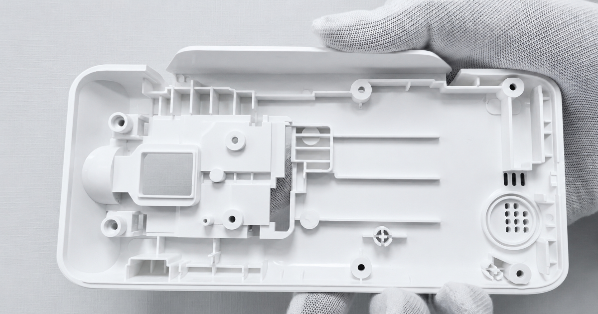
A payment device manufacturer developing a compact POS terminal for small retail and pop-up store applications required a production mold for the device bottom housing — a structural base component measuring 80 × 170 × 27 mm that serves as the mounting platform for every internal subsystem in the terminal. At 59.5 grams, the housing anchors the main control PCB, the thermal print head assembly, the battery compartment, the sensor module, and the communication interface board — all within a 2 mm wall thickness shell that must maintain dimensional stability across approximately 8–10 precision mounting holes and functional apertures.
Unlike a simple enclosure shell, a POS bottom housing is a chassis — it carries the mechanical loads of the print head mechanism during paper feed, absorbs impact energy when the device is moved or dropped on a shop counter, and provides the mounting datums that determine the alignment between the print head, the paper path, and the enclosure top cover. Misalignment of 0.3 mm at the print head mounting bosses produces a visible print skew — a defect immediately apparent to the end user on every receipt.
The housing also integrates three functional aperture types that must be molded-in rather than post-machined: a speaker grille array for audio transaction confirmation, sensor windows for paper detection and cover-open sensing, and heat dissipation vents for the thermal print head — the hottest component in the device, operating at 60–80°C during continuous receipt printing.
Part Specifications
| Parameter | Specification |
|---|---|
| Product | Mini POS terminal bottom housing |
| Dimensions | 80.0 × 170.0 × 27.0 mm |
| Weight | 59.5 g |
| Material | PC/ABS (engineering grade, UL94 V-2) |
| Wall thickness | 2.0 mm ±0.1 mm |
| Draft angle | 2–3° |
| Shrinkage | 0.5–0.7% (PC/ABS standard range) |
| Total hole count | 8–10 (screw bosses, sensor ports, mounting holes) |
| Screw specification | M3 threaded bosses |
| Functional features | Speaker grille, sensor windows, heat dissipation vents |
| Internal features | PCB mounting ribs, print head support columns, battery compartment walls, sensor module bracket |
| Surface finish | Spray-painted, Ra 1.6–3.2 μm substrate |
| Critical tolerance | ±0.3 mm (mounting datums ±0.2 mm) |
Engineering Approach
Material Selection — Why PC/ABS for a Chassis Application
The bottom housing is the most mechanically loaded component in a POS terminal. Three requirements drove the material selection to PC/ABS over standard ABS or HIPS:
Impact resistance. A mini POS terminal in retail and hospitality environments is moved between counter positions, stored on shelves, and occasionally knocked off a desk. The bottom housing — as the base that contacts the counter — absorbs the impact energy in any drop event. PC/ABS delivers notched Izod impact strength of 35–55 kJ/m², approximately 2–3× that of standard ABS at equivalent wall thickness. A 1.0 m drop test onto concrete, with the terminal landing on a bottom corner, is the worst-case loading condition that the housing must survive without cracking at the boss roots or vent edges.
Heat resistance near the print head. The thermal print head operates at 60–80°C during continuous receipt printing. The print head is mounted directly to bosses on the bottom housing — meaning the housing material at those bosses sees sustained temperatures of 60–70°C through conducted heat. Standard ABS has a heat deflection temperature (HDT) of approximately 85–95°C at 1.8 MPa — adequate but with limited margin. PC/ABS raises the HDT to 100–110°C, providing a 30–40°C margin above the operating temperature that ensures the boss threads do not creep or relax over the product lifetime.
Flame retardancy. While POS terminals are not subject to the same UL V-0 enclosure requirements as PIN entry devices, the power supply and battery charging circuitry inside the terminal make UL94 V-2 a prudent baseline — achievable with standard PC/ABS grades without the cost premium of V-0 FR formulations.
Mold Design for Multi-Feature Integration
The bottom housing packs approximately 8–10 precision features — screw bosses, sensor apertures, vent slots, and mounting ribs — into a 80 × 170 mm footprint. Each feature requires its own core pin, insert, or shut-off surface in the mold. The key design challenge is packing all of these features into a 2-cavity layout while maintaining adequate steel thickness between features for mold strength and cooling efficiency.
Boss design: All M3 screw bosses were designed with a base diameter of 6.0 mm (2× screw diameter) and a wall thickness of 1.2 mm (0.6× nominal wall) to prevent sink marks on the exterior painted surface. Bosses were positioned at least 8 mm from the housing side walls to maintain sufficient steel between the boss core pin and the cavity wall.
Speaker grille: The speaker grille array — approximately 15–20 holes at Ø1.2 mm with 1.5 mm pitch — was formed by H13 hardened core pins. At these diameters, pin deflection during injection is the primary failure mode. The pins were machined with a 0.5° taper and supported at both ends via a two-plate pin retainer system to prevent drift under melt pressure.
Heat dissipation vents: The vent slots near the print head mounting area are elongated rectangular apertures (12 × 3 mm, 3 slots in a row) formed by insert blocks. The slot orientation was aligned with the melt flow direction to prevent the flow front from splitting around each slot and creating weld lines on the opposite side of the housing.
Spray Painting Process
The bottom housing receives a matte black spray finish for both cosmetic consistency and surface durability. The painting process follows the standard production sequence:
| Step | Process | Specification |
|---|---|---|
| 1 | Surface preparation | Deionized water rinse, static removal |
| 2 | Drying | 60°C forced air, 10–15 min |
| 3 | Primer coat | PU-based primer, 10–15 µm DFT |
| 4 | Top coat | Matte black acrylic, 15–20 µm DFT |
| 5 | Curing | 60°C oven, 30 min |
| 6 | Inspection | 100% visual under 800 lux |
The Ra 1.6–3.2 μm substrate surface per surface finish standards — achieved through the mold cavity finish — provides adequate mechanical keying for paint adhesion without the need for chemical etching or flame treatment. The 2° draft angle on exterior walls and 3° on internal ribs ensures clean part release without drag marks that would telegraph through the paint.
Mold Design Details
| Parameter | Detail |
|---|---|
| Mold type | Two-plate injection mold |
| Cavities | 2 cavities |
| Mold steel | 718H pre-hardened (core & cavity) |
| Runner system | Naturally balanced H-pattern, cold runner |
| Gate type | Side gate on non-cosmetic internal surface |
| Cooling | Water cooling, 8 mm lines, 18 mm from cavity |
| Ejection | 6× Ø4 mm ejector pins + 4× blade ejectors per cavity |
| Core pins | H13 hardened inserts for screw bosses and sensor apertures |
| Speaker grille pins | H13, Ø1.2 mm, 0.5° taper, dual-end supported |
| Draft angle | 2° (exterior), 3° (internal ribs and bosses) |
| Surface | Ra 1.6–3.2 μm cavity face |
| Mold life | 300,000 shots |
Injection Molding Process
| Parameter | Value |
|---|---|
| Material | PC/ABS, engineering grade |
| Mold temperature | 50–60°C |
| Injection speed | Medium (to avoid gas marks in thin ribs) |
| Injection pressure | 80–110 MPa |
| Holding pressure | 60–80 MPa |
| Holding time | 15–20 s |
| Cooling time | 30–40 s |
| Total cycle time | 50–65 s |
| Material drying | 80°C × 4 hours, moisture <0.02% |
The mold temperature of 50–60°C — at the lower end of the PC/ABS range — was selected for two reasons: it accelerates skin formation on the 2 mm wall to reduce cycle time, and it minimizes the risk of gas marks (silver streaks) that PC/ABS can develop at higher mold temperatures when moisture is present. The medium injection speed prevents jetting at the gate and ensures that the melt front fills the 1.2 mm ribs uniformly without trapping air at the rib tips.
The 15–20 second holding time is longer than typical for a 2 mm wall part because the boss features create localized thick sections at the boss-to-wall junctions. These junctions cool more slowly than the nominal wall and require extended packing to prevent sink marks on the painted exterior surface opposite the bosses.
Quality Control
Each production batch undergoes a structured inspection protocol:
- Dimensional inspection — CMM sampling at 1:100 frequency; all mounting hole positions verified against ±0.3 mm (general) and ±0.2 mm (print head datums and PCB mounting)
- Boss thread verification — Go/No-Go gauge check on all M3 threaded bosses, 5 parts per shift
- Speaker grille inspection — 100% backlit visual for blocked or partially filled holes; pin gauge verification of Ø1.2 mm ±0.05 mm
- Surface appearance — 100% visual inspection under 800 lux for paint uniformity, flow marks, colour consistency, and surface defects
- Wall thickness verification — Ultrasonic thickness gauge at 5 measurement points on 1:200 samples; 2.0 mm ±0.1 mm
- Drop test — 1.0 m free fall onto concrete, 6 orientations; no cracking at boss roots, vent edges, or grille area
- Heat resistance — 72-hour thermal soak at 70°C with print head simulator mounted; no thread relaxation, no dimensional change >0.1 mm at mounting datums
- Paint adhesion — Cross-hatch tape test, adhesion grade ≥3 on a 5-grade scale
Results
| Metric | Target | Achieved |
|---|---|---|
| Dimensional tolerance (general) | ±0.3 mm | Cpk = 1.42 |
| Mounting datum accuracy (critical) | ±0.2 mm | Cpk = 1.35 |
| Wall thickness uniformity | 2.0 mm ±0.1 mm | 2.0 mm ±0.06 mm |
| Speaker grille open-hole rate | 100% | 99.7% |
| Paint adhesion (cross-hatch) | ≥Grade 3 | Grade 4 (no delamination) |
| Surface finish quality | No flow marks, no colour variation | ✅ Pass |
| Drop test (1.0 m) | No cracking at any feature | ✅ Pass, all orientations |
| Heat soak (70°C × 72 h) | No thread relaxation, Δ <0.1 mm | ✅ Pass |
| Per-part cost (incl. finishing) | ≤¥8.50 | ¥7.80 |
The 2-cavity mold entered production 7 weeks from project kickoff. The integrated multi-feature approach — molding the speaker grille, sensor apertures, heat dissipation vents, and all mounting bosses in a single shot — eliminated four secondary operations (grille drilling, sensor window machining, vent slot cutting, and boss threading) compared to a simplified shell design that would have required post-molding fabrication. The per-part cost of ¥7.80, including material, injection molding, spray painting, and quality inspection, met the target for a mid-volume payment device component.
This case study demonstrates JBRplas’s capability for structurally loaded, multi-feature POS terminal components — including PC/ABS material selection for impact and thermal requirements, integrated grille and vent molding, precision boss geometry for sub-system mounting, and matte black spray finishing with adhesion-grade validation.