Project Overview
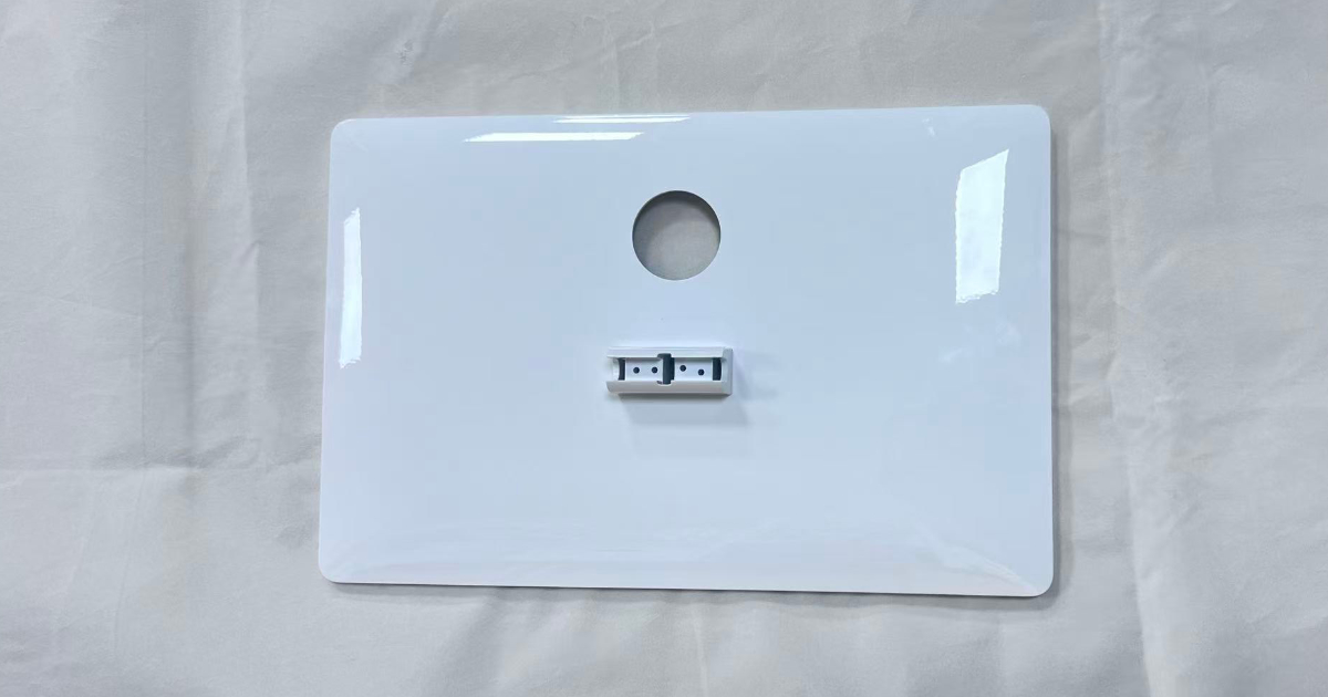
A POS equipment manufacturer developing a next-generation retail cash register system required a production mold for the monitor bottom housing — a large-format structural chassis measuring 290 × 190 × 38 mm that serves as both the mechanical foundation and the load-bearing base for the entire display assembly. At 180 grams with a 2.6 mm nominal wall, the housing must support the weight of the LCD panel, control board, power supply module, and touchscreen overlay while maintaining dimensional stability across a footprint that spans nearly 300 mm in the longest dimension.
A monitor housing of this size presents a different set of engineering challenges than a compact device enclosure. At 290 × 190 mm, the flat exterior surface is inherently prone to warpage — the differential cooling rate between the hotter center of the part and the cooler edges creates internal stress that distorts the part after ejection. The 2.6 mm wall thickness, while structurally adequate, creates a filling-to-cooling ratio that must be carefully managed: too fast an injection produces internal stress; too slow triggers premature freeze-off in the 0.9 mm rib features.
The client’s design also incorporates a large center circular aperture for the monitor stand mounting interface, snap-fit zones along the top edge for the bezel assembly, and an exterior surface that receives a white spray-paint finish. The painted surface means that any sink mark, flow line, or knit line on the exterior is visible in the final product — cosmetic control is inseparable from process control.
Part Specifications
| Parameter | Specification |
|---|---|
| Product | Retail cash register monitor bottom housing |
| Dimensions | 290.0 × 190.0 × 38.0 mm |
| Weight | 180 g |
| Material | ABS+PC (engineering grade) |
| Wall thickness | 2.6 mm nominal |
| Rib thickness | 0.9 mm |
| Rib height | 5.0 mm |
| Grid rib spacing | 18.0 mm |
| Edge fillet radius | R2.0 |
| Draft angle | 0.5° |
| Exterior finish | White spray-painted, flat surface with chamfer and fillet transitions |
| Functional features | Center circular aperture, top-edge snap-fit zones, grid-rib reinforcement, local support ribs |
| Exterior geometry | Square-corner rectangle, slight chamfer on edges, fillet transitions at corners |
| Application | POS cash register, retail point-of-sale display |
Engineering Approach
Material Selection — Why ABS+PC for a Large-Format Structural Housing
At 290 × 190 mm with a 2.6 mm wall, the housing requires a material that balances three competing demands: flowability to fill the large projected area, stiffness to resist deflection under the weight of the mounted display, and impact resistance to survive handling during assembly and in-service use on retail counters. ABS+PC was selected over standard ABS for three reasons:
Stiffness-to-flow ratio. A 290 mm flow length through a 2.6 mm wall requires a material with sufficient melt flow to reach the extremities of the cavity before the flow front freezes. Standard medium-impact ABS with an MFR of 15–20 g/10 min can fill this geometry, but at the cost of reduced stiffness. ABS+PC provides a flexural modulus of approximately 2,300–2,500 MPa — roughly 15–20% higher than standard ABS — while maintaining an MFR in the 12–18 g/10 min range suitable for large-area filling. The higher modulus translates directly to reduced deflection under the cantilevered load of the display assembly.
Impact resistance at corners. The square-corner rectangular geometry concentrates impact energy at the four corners during a drop event. A cash register monitor on a retail counter is exposed to accidental knocks from shopping baskets, cleaning equipment, and customer traffic — the bottom housing, as the component in contact with the counter surface, absorbs these impacts. ABS+PC delivers notched Izod impact strength of 40–55 kJ/m², providing a meaningful margin above the 20–30 kJ/m² typical of standard ABS. The R2.0 fillet at the corners further reduces the stress concentration factor at the impact points.
Paint adhesion without primer. The exterior surface receives a white spray-paint finish for cosmetic consistency with the monitor bezel and the retail environment. ABS+PC accepts acrylic-based topcoats with adequate adhesion on a properly prepared substrate surface, eliminating the need for a separate primer coat. This removes one process step, one quality gate, and the associated primer material cost from the finishing workflow.
The material selection for this part was driven fundamentally by the combination of large-format geometry, structural load requirements, and painted surface finish — a matrix that narrows the viable material window to ABS alloys with enhanced modulus and impact performance.
Warpage Control — Grid-Rib Architecture
The defining engineering challenge of this housing is flatness. At 290 × 190 mm with a 2.6 mm wall, the part has an aspect ratio (length to thickness) of approximately 112:1 — meaning the part is over 100 times longer than it is thick. In this regime, differential shrinkage between the hotter core and cooler skin of the wall thickness becomes the dominant source of post-molding distortion.
The client’s design addresses this through a grid-rib reinforcement architecture on the internal (non-cosmetic) face of the housing:
- Rib thickness: 0.9 mm — 0.35× the nominal wall, well within the 0.5–0.6× rule for rib design to avoid sink marks on the exterior surface. At 0.9 mm, the rib is thick enough to carry compressive and bending loads but thin enough that the rib root cools at substantially the same rate as the adjacent 2.6 mm wall, preventing the localized shrinkage differential that causes visible sink.
- Rib height: 5.0 mm — A 5:1 height-to-thickness ratio (5.0/0.9 ≈ 5.6:1) provides meaningful section modulus for bending stiffness without requiring excessive draft or creating filling challenges at the rib tip. Taller ribs (8–10 mm) would increase stiffness but risk short shots at the rib extremities due to premature freeze-off in the thin section.
- Grid spacing: 18.0 mm — The 18 mm pitch creates a network of intersecting ribs that subdivides the 290 × 190 mm panel into approximately 15 × 10 cells, each roughly 18 × 18 mm. This grid structure resists warpage through geometric constraint — each cell is small enough that the local shrinkage differential within a single cell produces negligible curvature, and the intersecting rib network prevents cumulative distortion from propagating across the full panel width.
The grid-rib approach is fundamentally a stiffness strategy. Rather than attempting to eliminate the thermal stress that causes warpage (which is inherent to the injection molding process for thin-wall large-area parts), the grid architecture provides sufficient geometric stiffness that the residual stress cannot overcome the part’s resistance to bending. The 0.5° draft angle on all vertical faces — ribs, walls, and bosses — ensures clean ejection without drag marks that would compromise the painted surface quality.
Snap-Fit Zones and Assembly Interface
The top edge of the housing incorporates snap-fit retention zones where the monitor bezel and front frame assembly attach to the bottom chassis during final assembly. These zones consist of cantilever snap-fit features molded directly into the housing wall — eliminating separate fasteners, reducing assembly part count, and removing the risk of metal screw bosses creating sink marks on the painted exterior.
The snap-fit geometry follows standard cantilever snap-fit design principles: the beam length of approximately 3–4 mm with a 0.6–0.8 mm undercut provides adequate retention force for a display bezel application (where the assembly load is primarily static and the service environment is a stationary retail counter). The snap-fit beams are oriented perpendicular to the mold opening direction, requiring side-action lifters in the mold — a design feature that adds tooling cost but eliminates the secondary assembly step of screw fastening along the top edge.
Center Aperture and Mold Filling Strategy
The large center circular aperture — the mounting interface for the monitor stand — creates a flow obstruction in the center of the cavity. The melt front must split around the core pin that forms this aperture, then rejoin on the opposite side. This flow-front reunion point is a weld line — a region where the two melt fronts meet at reduced temperature and pressure, producing a local reduction in mechanical strength and a visible line on the surface.
Two process decisions minimize the impact of this weld line:
Gate placement: The injection gate is positioned to produce a melt flow direction that places the weld line on a non-cosmetic internal surface rather than the painted exterior face. The gate is located on the internal ribbed side near the geometric center, so the flow front propagates outward from the center — the aperture core pin is downstream of the gate, and the weld line forms on the far side of the aperture on the internal surface, hidden by the monitor stand bracket during assembly.
Melt temperature at 245°C: ABS+PC typically processes at 230–260°C. Running at 245°C — in the mid-to-upper range — ensures the flow front retains sufficient temperature at the weld line to achieve adequate polymer chain entanglement across the interface. Too low a melt temperature produces a cold weld line with reduced strength; too high risks material degradation and surface splay. The 245°C barrel setting represents the balance point for this specific ABS+PC grade in this 290 mm flow-length geometry.
Edge Geometry — Chamfers, Fillets, and Ejection
The exterior surface features slight chamfers on the straight edges and R2.0 fillets at the corner transitions. These geometric features serve both cosmetic and functional purposes:
- R2.0 corner fillets reduce the stress concentration at the four corners — the highest-risk impact points for a rectangular enclosure. A sharp internal corner would act as a stress riser and a crack initiation site; the R2.0 radius distributes the impact load over a larger cross-sectional area.
- Chamfered edges provide a visual softening of the box geometry without the larger radius that a full fillet would require — a fillet radius large enough to visually soften a 290 mm edge would create a significantly thicker section at the corner, introducing a sink-mark risk on the painted surface.
- 0.5° draft on all vertical surfaces ensures clean part release. At 38 mm of draw depth, 0.5° draft produces a dimensional difference of approximately 0.33 mm between the top and bottom of the wall — tight enough for consistent assembly fit with the bezel but sufficient for reliable ejection from a polished P20 cavity.
Mold Design Details
| Parameter | Detail |
|---|---|
| Mold type | Two-plate injection mold |
| Cavities | 1-cavity (single cavity, part size driven) |
| Mold steel | P20 (core & cavity) |
| Runner system | Cold runner, direct sprue gate on internal face |
| Gate location | Internal ribbed side, near geometric center |
| Cooling | Water cooling, 10 mm lines, 22 mm from cavity |
| Ejection | Multi-point ejector pins on internal ribs and perimeter flange |
| Side actions | Lifters for top-edge snap-fit undercuts |
| Draft angle | 0.5° (exterior walls and ribs) |
| Surface finish | Polished cavity (Ra 0.8–1.6 μm exterior face) |
| Mold life | 300,000 shots |
The single-cavity configuration is driven by part size: at 290 × 190 mm, a single cavity already requires a mold base in the 500–600 mm range, and a two-cavity layout would demand a press capacity exceeding 400 tonnes — disproportionate to the 180 g shot weight. The single-cavity approach with a 52-second cycle time balances tooling cost, press utilization, and production throughput for the client’s mid-volume requirement.
Injection Molding Process
| Parameter | Value |
|---|---|
| Material | ABS+PC, engineering grade |
| Barrel temperature | 245°C (zoned: 230/240/245/245/240°C) |
| Mold temperature | 58°C |
| Injection pressure | 800–1,200 bar (80–120 MPa) |
| Injection speed | Medium-high |
| Holding pressure | 35–55% of shot volume |
| Holding time | 12 s |
| Cooling time | 22 s |
| Total cycle time | 52 s |
| Material drying | 80°C × 4 hours, moisture <0.02% |
The 245°C barrel temperature represents the engineering balance for ABS+PC in this geometry. Running at the mid-to-upper range of the ABS+PC processing window provides the melt fluidity needed for a 290 mm flow length through a 2.6 mm wall, while staying 15–20°C below the degradation threshold of the PC component. The temperature profile — 230°C at the feed zone rising to 245°C at the metering zone and nozzle — ensures progressive melting without overheating the material at the feed throat where residence time is longest.
The 58°C mold temperature is set at the lower end of the ABS+PC mold temperature range (typically 50–80°C). A moderate mold temperature accelerates skin formation on the 2.6 mm wall for cycle time efficiency, while maintaining sufficient cavity surface temperature that the 0.9 mm rib sections fill completely before the melt freezes. Raising the mold temperature to 70–80°C would improve rib fill reliability but would extend the 22-second cooling time — the cycle time penalty would increase per-part cost without a corresponding quality improvement, since the rib fill is already achieved at 58°C through the combination of medium-high injection speed and 245°C melt temperature.
The holding pressure of 35–55% of shot volume — approximately 280–440 bar at the hold stage — with a 12-second hold time addresses the primary injection molding defect risk in this part: sink marks on the painted exterior surface. The 2.6 mm wall-to-0.9 mm rib junctions are localized thick sections that cool more slowly than the surrounding material. The extended hold time ensures that the gate remains open long enough for these junctions to receive continued melt packing as the material shrinks during cooling, preventing the volumetric deficit that produces visible sink.
The 22-second cooling time reflects the thermal mass of a 180 g part with a 2.6 mm wall — substantially longer than the 12–15 seconds typical for a 2 mm wall at equivalent weight. The 52-second total cycle time (injection 3–4 s + hold 12 s + cooling 22 s + mold open/close/eject 14–16 s) delivers a production rate of approximately 69 parts per hour from the single-cavity mold.
Quality Control
Each production batch undergoes a structured inspection protocol aligned with the requirements of a cosmetic structural housing for retail equipment:
- Dimensional inspection — CMM full-layout on first article and 1:200 sampling; overall dimensions verified against 290.0 ± 0.3 × 190.0 ± 0.3 × 38.0 ± 0.2 mm; center aperture diameter and position verified against ±0.2 mm
- Flatness measurement — Dial indicator sweep across the 290 × 190 mm exterior face on 1:100 samples; flatness deviation <0.5 mm across the diagonal; grid-rib zone inspected for local depression or distortion
- Snap-fit verification — Go/No-Go gauge check on snap-fit undercut dimensions, 5 parts per shift; assembly fit test with bezel sample on 1:200 frequency
- Surface appearance — 100% visual inspection under 800 lux for paint uniformity, sink marks, flow lines, knit lines, and colour consistency on the painted exterior face
- Paint adhesion — Cross-hatch tape test on 1:200 samples; adhesion grade ≥3 on a 5-grade scale
- Drop test — 0.8 m free fall onto concrete, 6 orientations (4 corners + face + edge); no cracking at snap-fit roots, rib intersections, or aperture edge
- Load deflection — Static load test with 5 kg distributed weight simulating display assembly; deflection at center of housing <0.3 mm
- Thermal cycling — -10°C to +50°C, 24 cycles; no dimensional change exceeding 0.2 mm, no paint delamination, no snap-fit relaxation
- Weight consistency — Shot-to-shot weight variation <1.5%
Results
| Metric | Target | Achieved |
|---|---|---|
| Overall dimensional tolerance | ±0.3 mm | Cpk = 1.38 |
| Center aperture position | ±0.2 mm | Cpk = 1.44 |
| Flatness (290 mm diagonal) | <0.5 mm | 0.32 mm average |
| Surface finish (painted) | No sink marks, no flow lines | ✅ Pass |
| Paint adhesion (cross-hatch) | ≥Grade 3 | Grade 4 |
| Drop test (0.8 m, 6 orientations) | No cracking | ✅ Pass, all orientations |
| Static load deflection (5 kg) | <0.3 mm | 0.18 mm |
| Thermal cycling (-10°C to +50°C) | Δ <0.2 mm | Δ = 0.09 mm |
| Shot-to-shot weight variation | <1.5% | 1.1% |
| Cycle time | ≤55 s | 52 s |
The grid-rib reinforcement architecture proved effective in controlling warpage on the 290 × 190 mm exterior face. The combination of 0.9 mm rib thickness (0.35× nominal wall), 18 mm grid spacing, and 5.0 mm rib height produced flatness deviation of 0.32 mm across the full diagonal — well within the 0.5 mm target and below the threshold where flatness deviation would be visible on the painted surface or affect bezel assembly fit.
The 0.5° draft angle, combined with a polished P20 cavity surface, delivered consistent part release without drag marks or scuffing on the exterior surface — critical for the painted finish, where any ejection-related surface defect telegraphs through the paint layer. The R2.0 corner fillets performed as designed in the drop test, with no crack initiation at any corner across all six impact orientations.
The 52-second cycle time on a single-cavity mold provides production throughput of approximately 69 parts per hour — sufficient for the client’s mid-volume retail equipment production schedule with capacity for demand fluctuations.
This case study demonstrates JBRplas’s capability for large-format structural injection molding — including ABS+PC material selection for stiffness-impact balance, grid-rib reinforcement architecture for warpage control on thin-wall panels exceeding 100:1 aspect ratio, snap-fit integration for assembly efficiency, painted Class A surface with sink-mark prevention, and dimensional control across a 290 mm footprint.