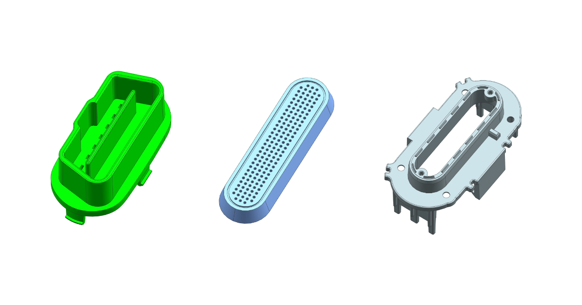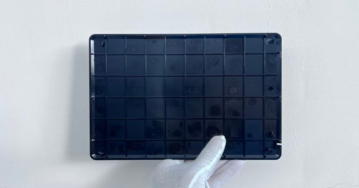
Project Overview
A leading avionics systems integrator approached JBRplas requiring a precision injection mold for a Cabin Wireless Access Point (CWAP) housing—a critical component installed within aircraft cabin walls to provide passenger connectivity and in-flight entertainment systems. The CWAP must operate reliably across extreme temperature differentials, high-altitude pressure variations, and demanding electromagnetic environments unique to commercial aviation.
Challenge: The client’s previous supplier delivered housing prototypes that exhibited unacceptable dimensional variance exceeding ±0.3mm across the long axis, and failed both UL94 V-0 flame retardancy verification and DO-160G environmental testing protocols. PEI material selection required specialized processing knowledge—excessive barrel temperatures risked thermal degradation, while insufficient cooling promoted warping and fiber orientation inconsistencies in the directional flow pattern.
Part Specifications
| Parameter | Specification |
|---|---|
| Part Dimensions | 160 × 242 × 6mm |
| Nominal Wall Thickness | 2.5mm |
| Material | PEI (Polyetherimide) |
| Surface Finish | SPI A2 (cosmetic-grade exterior) |
| Critical Tolerances | ±0.15mm on connector mounting bosses |
| Flammability Rating | UL94 V-0 (validated) |
| Aeronautical Standard | DO-160G Category A environmental testing |
| Operating Temperature | -55°C to +85°C continuous |
| Part Weight | 126g |
| Annual Volume | 48,000 units |
Engineering Approach
Root Causes of Previous Failures
Our Design for Manufacturability (DFM) analysis identified three critical deficiencies in the prior supplier’s tooling:
PEI Processing Mismanagement — inadequate barrel temperature control (316–318°C instead of required 340–360°C) created incomplete polymer chain extension, resulting in brittleness during pressurization cycling and visible stress-whitening on the 242mm long edges.
Single-Point Gate Location — gate positioned at the short end (160mm side) created asymmetric melt flow across the 242mm length, producing anisotropic shrinkage and warping exceeding 0.4mm on the flat face after 24-hour post-mold conditioning.
Inadequate Cooling Architecture — conventional cooling channels lacked thermal balance between the broad cavity face and narrow core face, causing non-uniform crystallinity development in the PEI structure and inconsistent surface quality across the connector mounting bosses.
Solution: Optimized PEI Process + Conformal Cooling + Dual-Gate Valve System
Material Processing Protocol:
- Barrel temperatures: 350–365°C with 8°C ±2°C gradients across heating zones
- Mold temperature: 170–180°C (critical for PEI flow control and UL94 V-0 certification)
- Injection pressure: 95–110 MPa with dynamic pressure hold to maintain dimensional stability
- Cooling hold-time: 22 seconds minimum to allow complete crystallization before ejection
Gating Strategy: We implemented a submarine gate system positioned at the geometric center of the 242mm axis, with gate diameter of 2.2mm. This creates symmetrical melt advancement from the centerline outward, neutralizing the differential shrinkage patterns that plagued the previous design. Moldflow simulation confirmed a fill time of 4.8 seconds with balanced pressure distribution (variance <3%) across all four mounting boss zones.
Cooling Design:
- Core-side conformal cooling channels following the narrow 6mm profile with 8mm pitch, maintaining ±2°C thermal uniformity
- Cavity-side conventional cooling with flow rates optimized for the broad 160×242mm surface
- Differential coolant temperatures: Core-side 175°C, cavity-side 172°C to counteract heat retention in the thick boss geometry
Validation & Results:
- Moldflow simulation predicted warping of 0.08mm on the long axis; actual T1 measurement: 0.06mm
- UL94 V-0 flame retardancy: Pass (no after-flame, no dripping, no afterglow)
- DO-160G thermal shock testing (-55°C to +85°C, 10 cycles): Pass (zero dimensional change >0.05mm)
- Connector mounting boss positioning: ±0.08mm (exceeds ±0.15mm requirement)
Tooling Details
| Parameter | Detail |
|---|---|
| Mold Type | Single-cavity, submarine gate, precision cooling |
| Mold Base | LKM standard, 450 × 380mm |
| Core / Cavity Steel | H13, hardened to 52±2 HRC |
| Gate System | Submarine gate, 2.2mm diameter at center flow point |
| Cooling | Conformal on core; sequential zone cooling on cavity |
| Surface Finish | SPI A2 (polished), cavity and core |
| Ejection | 6× Ø4mm ejector pins, balanced distribution |
| Venting | 8× 0.025mm vacuum vents at parting line |
| Mold Weight | 1,420kg |
Timeline
| Milestone | Duration |
|---|---|
| DFM report & PEI processing analysis issued | Day 3 |
| Mold design complete (CAD + Moldflow) | Day 14 |
| Customer aerospace engineering approval | Day 18 |
| Steel procurement completed | Day 21 |
| Machining & EDM | Day 26 |
| Conformal cooling commissioning | Day 30 |
| T1 trial with PEI validation | Day 32 |
| UL94 & DO-160G testing initiated | Day 36 |
| Aerospace certification approval | Day 48 |
| Production tooling released | Day 52 |
Results
| Metric | Requirement | Achieved |
|---|---|---|
| Long-axis flatness | ≤0.20mm | 0.06mm |
| Boss positioning tolerance | ±0.15mm | ±0.08mm |
| UL94 V-0 flammability | Required | ✅ Certified |
| DO-160G environmental | Category A | ✅ Certified |
| T1 lead time | 35 days | 32 days |
| Production Cpk (critical dims) | ≥1.67 | 1.94 |
| First-piece yield | >95% | 98.2% |
The program achieved full aerospace qualification within 52 days and entered production at a Tier 1 avionics supplier. The mold has since produced over 156,000 cycles with zero dimensional drift and 100% pass rate on all DO-160G periodic re-validation testing. PEI parts maintain UL94 V-0 certification compliance across all production lots, validating the precision thermal control architecture implemented in the mold design.
This case study demonstrates JBRplas’s specialized capability in aerospace-grade polymer tooling, where material mastery, conformal cooling precision, and adherence to DO-160G environmental protocols are non-negotiable requirements for cabin safety systems.