Project Overview
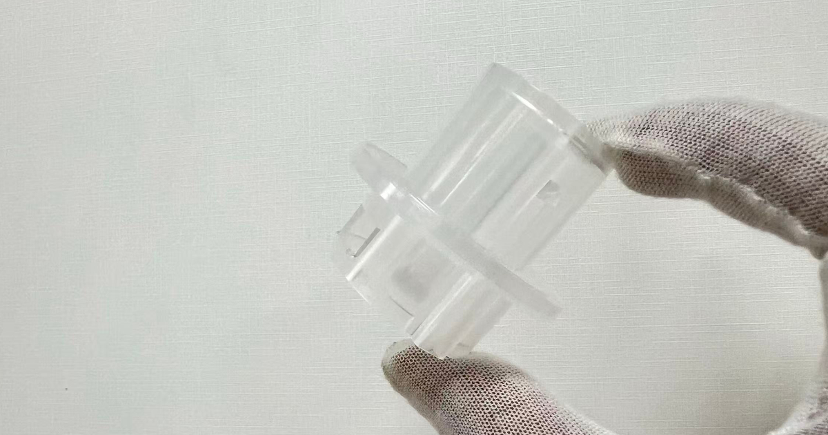
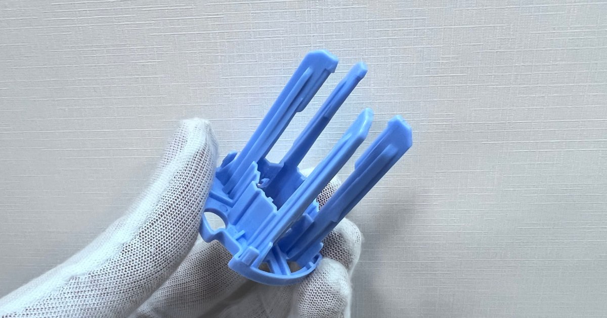
A European medical device manufacturer required a high-precision internal support bracket for a new-generation blood glucose meter. The component serves as the structural frame inside the handheld device, accurately positioning the PCB, test strip module, and battery assembly while maintaining dimensional stability throughout the product’s multi-year lifecycle.
Unlike an external enclosure, the internal bracket is a functional component — every mounting boss, snap-fit tab, and support rib directly affects assembly accuracy and long-term measurement reliability. A bracket that drifts by 0.05mm can shift the test strip connector relative to the housing slot, causing strip insertion errors in the field.
The part combines four molding challenges in a single component: a uniform 0.8mm wall thickness throughout, four long slender support arms with high aspect ratios, multiple snap-fit locking features formed at the parting line, and dimensional control within ±0.05mm on all critical assembly interfaces.
Part Specifications
| Parameter | Specification |
|---|---|
| Part | Blood glucose meter internal support bracket |
| Dimensions | 40.7 × 40.7 × 52.0 mm |
| Weight | 7.5 g |
| Material | Medical grade PC (Polycarbonate, UL94 V-0 optional) |
| Wall thickness | 0.8 mm nominal |
| Critical tolerance | ±0.05 mm on all assembly features |
| Surface finish | SPI-B2 fine finish |
| Texture | None (functional surface) |
| Annual volume | 500,000 parts |
Manufacturing Challenges
1. Ultra-Thin Wall Filling
A uniform 0.8mm wall thickness across the entire bracket — including ribs, bosses, and snap-fit arms — demands fast cavity filling with balanced melt flow. At this wall section, the melt front cools rapidly. Any hesitation, flow imbalance, or inadequate packing pressure produces short shots or incomplete fill in the thin rib sections farthest from the gate.
Maintaining consistent part weight and dimensional repeatability at 0.8mm requires a processing window with tight control over injection velocity, melt temperature, and packing pressure — a narrower window than a standard 2.0mm part.
2. Long Slender Support Arms
The four vertical support arms are long, narrow features with high aspect ratios — the kind of geometry that amplifies every processing variable into a quality problem. Potential injection molding defects include core deflection during filling (the melt pressure bends the slender core pin), uneven shrinkage causing the arms to pull out of straightness, sink marks at the arm-to-body junction, and flash if clamping force or packing pressure is not precisely controlled.
Straightness of these arms is functionally critical: they position the PCB and test strip module inside the device. An arm that leans by even 0.1mm can misalign the entire internal assembly.
3. Assembly-Critical Tolerance Stack
The bracket interfaces with the PCB mounting bosses, test strip module alignment features, battery compartment retention clips, and the outer housing snap-fit receivers — all in a compact 40.7 × 40.7mm footprint. Maintaining ±0.05mm across all these interfaces requires the mold to produce consistent parts cavity-to-cavity, shot-to-shot, and batch-to-batch — a level of injection molding tolerance control that demands both precision tooling and a locked process window.
4. Polycarbonate Moisture Sensitivity
Medical-grade PC provides the stiffness, dimensional stability, and biocompatibility the application demands — but like all medical-grade resins, it is highly sensitive to moisture during processing. Inadequate drying produces splay marks (visible surface streaking from hydrolyzed resin), internal bubbles that reduce structural strength, and loss of mechanical properties in the molded part. For a thin-wall structural bracket, there is no margin for degraded material.
Mold Design Solution
Balanced 2-Cavity Layout
A naturally balanced H-pattern cold runner system was designed to deliver equal flow length, equal pressure drop, and equal fill time to both cavities. Natural balance — as opposed to artificially balanced runners with restrictive features — ensures consistent part weight and uniform shrinkage cavity-to-cavity without introducing shear imbalance that can cause differential material degradation.
The pin gate was positioned at a non-functional surface on the bracket body, away from the snap-fit arms and mounting bosses, keeping gate vestige outside assembly-critical zones.
Optimized Cooling for Thin-Wall PC
Cooling channels were positioned as close to the cavity as steel strength allows — approximately 1.5× the channel diameter from the cavity surface. For a thin-wall part like this, conformal cooling principles were applied to maintain uniform heat extraction despite the varying geometry of ribs and bosses. The cavity side (exterior surfaces) runs 5°C cooler than the core to bias the part toward the non-functional side during shrinkage.
Precision Venting at Rib Ends
Micro vents at 0.015mm depth were positioned near the ends of each thin rib and snap-fit feature — the last places to fill, where trapped air is most likely to cause burn marks or short shots. Venting at these locations allowed air to escape efficiently ahead of the melt front, eliminating gas traps without producing flash at PC processing pressures.
Moldflow Simulation Before Steel Cutting
Prior to tooling, full Moldflow simulation was performed to validate:
- Filling balance across both cavities
- Weld line location and strength at the rib intersections
- Pressure distribution and injection pressure requirement
- Air trap prediction and vent positioning
- Cooling efficiency and cycle time estimate
- Warpage tendency and magnitude
Simulation results confirmed the gate position, runner balance, and cooling layout before any steel was cut — eliminating the iterative tool trials that would otherwise be needed to dial in a thin-wall mold of this complexity.
Tooling Details
| Parameter | Detail |
|---|---|
| Mold type | 2-cavity cold runner, pin gate |
| Mold base | S50C |
| Core / cavity steel | H13 (1.2344), hardened |
| Runner | H-pattern, naturally balanced |
| Gate | Pin gate, positioned away from functional features |
| Cooling | Conformal-positioned channels, cavity side biased 5°C cooler |
| Venting | 0.015mm micro vents at rib ends and snap-fit features |
| Ejection | Ejector pins + sleeve ejectors on bosses |
| Surface | SPI-B2 fine finish |
| Mold life | 500,000 shots |
Sleeve ejectors were specified for the four mounting bosses rather than standard ejector pins — providing uniform ejection force around each boss circumference and preventing the ejection distortion that can occur when thin-wall parts are pushed off the core unevenly.
Injection Molding Process
| Parameter | Value |
|---|---|
| Injection machine | 120 Ton servo-driven |
| Injection pressure | 90–120 MPa |
| Mold temperature | 90–110°C |
| Melt temperature | 290–310°C |
| Cycle time | 24–28 seconds |
| Drying condition | 120°C × 4–6 hours, dew point ≤ −40°C |
| Target moisture content | <0.02% |
The servo-driven injection machine provides the precise injection velocity control required for thin-wall filling — servo motors respond faster than hydraulic systems to velocity transitions, reducing the risk of a hesitation mark or flow front stall at the thin rib sections.
Quality Control
Each production batch undergoes comprehensive inspection:
- CMM dimensional measurement — all critical assembly interfaces verified against the 2D drawing
- First Article Inspection (FAI) — full dimensional report per AS9102-style format, all drawing dimensions measured and recorded
- Appearance inspection — 100% visual check for splay, burn marks, short shots, and flash under 500 lux lighting
- Assembly verification — functional fit test with client-supplied PCB, test strip module, and battery assembly gauges
- SPC process monitoring — critical dimensions tracked throughout production; Cp/Cpk calculated quarterly
Critical dimensions — mounting boss positions, snap-fit arm spacing, and PCB support surface flatness — are monitored with SPC control charts to ensure long-term process capability and early detection of tool wear trends.
Results
| Metric | Target | Achieved |
|---|---|---|
| Wall thickness consistency | 0.8mm nominal | 0.78–0.83mm across all sections |
| Dimensional tolerance (critical) | ±0.05mm | Cpk = 1.52 |
| Support arm straightness | ≤0.08mm deviation | ≤0.05mm |
| Snap-fit performance | 100% engagement in assembly test | ✅ 100% |
| Cavity weight variation | <1.5% | 0.9% |
| Cosmetic defect rate | <0.5% | 0.22% |
| Annual production capacity | 500,000 | ✅ Achieved |
The 2-cavity mold entered stable production and has reliably supplied over 500,000 parts per year for the client’s blood glucose meter assembly line. Dimensional Cpk remains above 1.50 across all critical features after 18 months of continuous production.
This case study demonstrates JBRplas’s precision molding capability for thin-wall medical device structural components — including 0.8mm uniform wall molding, balanced multi-cavity tooling, Moldflow-validated cooling design, and ±0.05mm tolerance control for assembly-critical features in medical-grade polycarbonate.