Project Overview
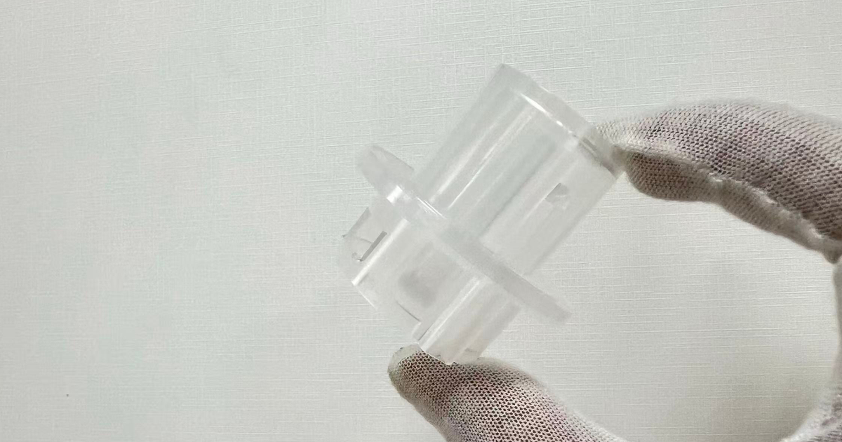
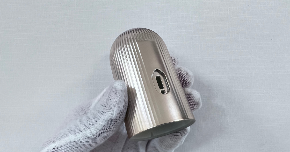
A beauty electronics brand developing a next-generation handheld microcurrent facial massager required a production mold for the device housing — a streamlined cylindrical enclosure with decorative longitudinal ribs, a deep cavity profile, and a side USB charging port. The device is a premium consumer product sold in Europe and North America, where cosmetic appearance is the primary purchasing signal. The housing must look flawless under retail lighting: no sink marks, no gate witness, no flow lines, and a uniform metallic gold painted finish across the curved surface. The housing combines four engineering challenges in a single molding: a 75mm deep cavity with a diameter of only 43.8mm, continuous vertical decorative ribs across the curved exterior, two precision side openings formed at the parting line by external sliders, and a Class A painted surface that amplifies every subsurface defect. The device carries an IPX2 waterproof rating — protected against dripping water at a 15° tilt — which adds an additional sealing requirement to the housing design. A sink mark invisible on an unpainted textured part becomes a high-contrast defect under metallic paint.
Challenge: The deep cavity geometry — a 1.7:1 height-to-diameter ratio — creates inherent risks of core deflection, uneven cooling, air trapping, and difficult ejection. The decorative ribs crossing the curved surface must fill completely without weld lines. The painted surface leaves zero tolerance for subsurface defects. Achieving stable production at 200,000 parts per year required a cooling design that balanced the deep core, a slider system that produced flash-free side openings, and a process window locked to cosmetic-grade consistency.
Part Specifications
| Parameter | Specification |
|---|---|
| Part | Handheld microcurrent beauty device housing |
| Dimensions | Ø43.8 × 75mm |
| Wall thickness | 2.35mm nominal |
| Material | ABS, high gloss injection grade |
| Part weight | 21.65g |
| Exterior finish | Metallic gold painting, Class A cosmetic |
| Decorative features | Continuous longitudinal ribs across curved surface |
| USB port | Side opening, ±0.05mm dimensional accuracy |
| Button opening | Side opening, ±0.05mm dimensional accuracy |
| Waterproof rating | IPX2 (dripping water at 15° tilt) |
| Cosmetic standard | Class A on all exterior visible surfaces |
| Annual volume | 200,000 pieces |
| Export market | Europe & North America |
Engineering Approach
Deep Cavity Cooling and Core Stability
The housing measures 75mm in height with a diameter of 43.8mm — a 1.7:1 aspect ratio that makes the core unusually deep for a part of this diameter. Three risks must be managed simultaneously:
Core deflection. At 75mm projection with a 2.35mm wall, the incoming melt at 230–245°C exerts uneven pressure on the core as the flow front advances around the cylindrical geometry. A core shift of even 0.05mm produces a wall thickness variation that the painted surface will reveal as a gloss differential — the thinner wall cools faster and produces a slightly different surface texture post-painting.
The core was machined from H13 hardened to 48–50 HRC with a precision-ground locating diameter at the base. The core seat in the mold base was wire-EDM cut to a H7/g6 sliding fit, providing radial support across the full 15mm embedment depth. Moldflow simulation of the fill pattern confirmed balanced pressure distribution around the core circumference at the selected gate position.
Uneven cooling. A conventional bubbler cooling design — a straight tube up the center of the core with water returning through the annulus — cools the base of the core effectively but leaves the tip 10–15°C hotter. The tip of the core forms the top curved surface of the housing, which is the most visible surface to the user.
We implemented an optimized deep core cooling circuit with an extended bubbler reaching to within 8mm of the core tip, an independent cooling circuit with dedicated temperature control, and enhanced cooling around the rib section where the additional steel volume creates a localized heat sink. The independent circuit allows the core temperature to be set 5–8°C lower than the cavity temperature, compensating for the higher heat load on the core side.
Air trapping. The deep, closed-end cavity geometry traps air at the tip of the core as the melt front advances. We added engineered venting at the parting line and at the core tip via a vent pin — a 3mm diameter insert with a 0.02mm deep vent slot that allows air to escape while preventing plastic flash.
Decorative Rib Filling
The exterior of the housing features continuous vertical ribs extending across the curved cylindrical surface. These ribs are cosmetic features — 0.5mm high, 0.8mm wide, spaced approximately 3mm apart — that create a linear highlight pattern across the painted finish.
Rib filling challenges:
- Uniform fill across curvature. As the melt front advances upward through the 75mm cavity, the ribs on the outer surface must fill simultaneously without trapping air at the rib tips. A rib that fills last — because the local flow resistance is higher — will show a short shot or a hesitation mark that the metallic paint will not hide.
- Weld line avoidance. The melt front splits around the core and rejoins. The gate position was selected so the primary weld line falls on the rear face of the housing — opposite the USB port — where it is least visible and can be oriented vertically to minimize its cosmetic impact.
- Sink mark prevention. The rib-to-wall thickness ratio was kept at 0.34:1 (0.8mm rib width to 2.35mm wall) — below the 0.5:1 threshold where sink marks begin to appear on the opposite surface.
Side Opening Slider System
The housing has two side openings formed at the parting line, each requiring a precision external slider:
USB charging port. A rectangular opening — 8.2 × 4.5mm, with ±0.05mm tolerance on the width and ±0.08mm on position relative to the bottom datum. The USB port must align precisely with the internal PCB connector, and the opening edges must be flash-free for a clean painted finish.
Button switch opening. A circular opening — Ø6.5mm, with ±0.05mm tolerance on diameter and ±0.08mm on position — for the device power/function button. The button opening must produce a clean edge without flash or burr that would interfere with button travel or create a visible cosmetic defect around the button perimeter.
Both openings are formed by two external sliders — one per opening — moving perpendicular to the mold opening direction:
- Slider 1 (USB port): Forms the USB charging port opening. The slider face that contacts the core has a precision shut-off surface to prevent flash at the parting line.
- Slider 2 (Button opening): Forms the button switch opening. Shut-off geometry matches the cylindrical curvature of the housing surface to maintain the continuous painted finish around the button opening.
Both sliders are guided by hardened SKD61 angle pins with bronze wear plates. Slider travel is limited by positive stops. The shut-off surfaces were spark-eroded to a 0.01mm flatness tolerance and verified on CMM before mold assembly. The sliders retract before ejection so the part can be stripped from the core without interference.
For the IPX2 waterproof rating — protection against dripping water when tilted up to 15° — the housing shell itself provides the primary water deflection. The side openings are sealed by the USB connector gasket and the button membrane respectively, which are assembled components in the finished device. The molded housing must provide clean, dimensionally accurate opening geometry so the seals seat correctly without gaps or deformation.
Gate Selection for Cosmetic Parts
A submarine gate was selected for two reasons:
- Automatic separation. The gate shears off during ejection, eliminating the manual gate trimming step that would leave a witness mark on a cosmetic surface. A side gate would require an operator to trim the gate and risk damaging the surface finish at the gate location.
- Gate location on a non-visible surface. The submarine gate feeds into the bottom face of the housing — the surface that mates with the base cap and is never visible to the user. The gate mark is buried in the assembly joint.
The gate diameter was sized at 1.2mm — large enough to prevent premature freeze-off during packing (which would produce sink marks on the adjacent wall) but small enough to shear cleanly during ejection without pulling a crater from the part surface.
Painting Process Integration
The metallic gold painting process is not simply applied to molded parts — it requires the molded parts to meet a higher standard than parts that will receive a textured or unpainted finish. Every subsurface defect becomes more visible after painting:
| Defect | Unpainted (VDI 24 Texture) | Metallic Gold Paint |
|---|---|---|
| Sink mark, 0.02mm deep | Invisible — texture masks it | Visible — metallic flake orientation changes over sink area |
| Flow line | Partially masked by texture | Amplified — paint follows surface contour |
| Gate vestige, 0.05mm high | Flush-trimmed, texture masks remnant | Visible as a local gloss change |
| Weld line | Visible as a faint line | Amplified — metallic flakes align along the weld line |
The molded parts undergo a surface inspection before painting. Parts with any of the above defects at the visible threshold are rejected before painting — it is cheaper to regrind an unpainted part than to paint, inspect, and reject a painted part.
The painting process sequence: injection molding → gate trimming → surface inspection → painting (metallic gold, 2-coat: base color + clear) → oven curing (65°C, 30 min) → final inspection → assembly.
Tooling Details
| Parameter | Detail |
|---|---|
| Mold type | Two-plate, 1-cavity, cold runner |
| Mold base | S50C, 350 × 350mm |
| Core steel | H13, 48–50 HRC |
| Cavity steel | 1.2344 |
| Slider steel | SKD61, hardened |
| Runner | Cold runner, Ø4mm |
| Gate | Submarine gate, Ø1.2mm, bottom face |
| Sliders | 2 external sliders (USB port + button opening), hardened angle pins with bronze wear plates |
| Cooling | Optimized deep core cooling with extended bubbler; independent core and cavity circuits |
| Ejection | 4× Ø3mm ejector pins (bottom face) + 2× Ø2.5mm ejector pins (internal) |
| Venting | Parting line vents + core tip vent pin, 0.02mm depth |
| Cavity surface | SPI A-2 polish (paint-ready) |
| Mold weight | 380kg |
Results
| Metric | Target | Achieved |
|---|---|---|
| USB port width | 8.20mm ±0.05mm | Cpk = 1.58 |
| Button opening diameter | Ø6.50mm ±0.05mm | Cpk = 1.62 |
| USB port position | ±0.08mm | ±0.04mm |
| Button opening position | ±0.08mm | ±0.05mm |
| Wall thickness variation (radial) | <0.08mm | 0.04mm mean |
| IPX2 waterproof | Dripping water at 15° tilt | Pass — no ingress |
| Cosmetic rejects (pre-paint) | <1.0% | 0.42% |
| Cosmetic rejects (post-paint) | <1.5% | 0.71% |
| Rib fill | 100%, no short shots | 100%, all cavities |
| Paint adhesion (cross-cut test) | ISO Class 0 | ISO Class 0 |
| Cycle time | <32 s | 29 s |
| T1 lead time | 30 days | 28 days |
| Production capability | 200,000/year | Confirmed, stable |
The mold entered production 6 weeks from project kickoff. The client’s device launched in Europe and North America with zero field returns attributed to housing cosmetic defects in the first 12 months of sales. JBRplas continues to supply production quantities under an annual forecast agreement.
This case study demonstrates JBRplas’s precision molding capability for cosmetic consumer electronics — including deep cavity core design, decorative rib filling, external slider side openings with IPX2 waterproofing, and Class A painted surface quality on ABS for premium personal care devices.